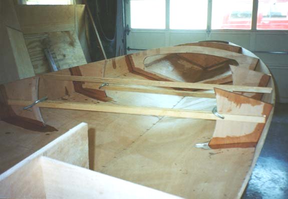
With the bottom and side pieces stitched up it was time to begin working on the bulkheads. I use the term bulkhead loosely to include all components of the boat that are vertical. This includes the bow, transom, flotation bulkhead, front cockpit (storage) bulkhead, knees, motor bracket bulkhead, longitudinals, and laterals.
My friend Jeff Smith gave me a lot of great tips for this portion of the project. Many of the techniques I cover in this section and others are a direct result of him. When I use the word I, you can frequently substitute Jeff for more accuracy.
The plans contain all the dimensions needed to layout the bulkheads. These are cut from 3/4" plywood. The first step before doing any cutting was to spread the hull out according to the dimensions of the bulkheads. Using some 1"x2" Doug Fir and other scrap I cut pieces to the same widths as the bulkheads and tacked them into place with finishing nails.
The first bulkhead cut was the bow. Using the dimensions from the blueprints I penciled the bulkhead on my 3/4" ply and cut it out. To minimize wastage of plywood I laid the bow bulkhead out on the sheet of plywood where the storage bulkhead was to be cut. By placing the bow bulkhead in the center of the storage bulkhead I was using scrap plywood. The center of the storage bulkhead is cut out for access to the storage area. I laid out the storage bulkhead in pencil and made sure I wasn't cutting in the wrong place. I left the top of the bow bulkhead higher than what the plans called for. After reviewing the plans I decided I wanted the decks a little higher with slightly more curvature. Initially all of the bulkheads were cut taller than the plans called for to allow for this modification. After the bow bulkhead was cut I stitched it into place with the bottom and side pieces. I cut another bow bulkhead (slightly smaller) and laminated it to the first after all the filleting process was completed. This was done to provide extra strength where the bow eye would be.

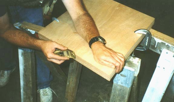
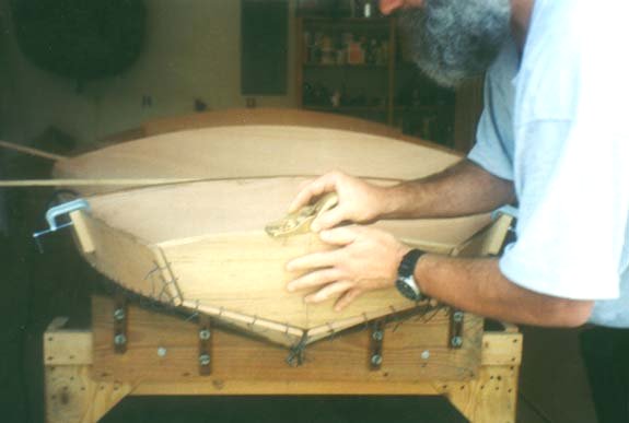
The next component worked on was the transom. Because the Scaup has a motor well the transom consists of two pieces. Once again, using the blueprints I laid out the two pieces on 3/4" plywood. When cutting them out I left the tops higher than the plans called for so more curvature could be added to the decking, as previously mentioned. After they were cut I laid the two pieces on top of each other, clamped them together, and planed the edges to ensure symmetry. The below picture is of the motor well sides but demonstrates how to ensure symmetry. This should be done on all components that are similar.

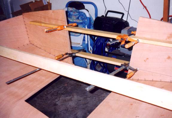
After they were cut and planed I stitched them into place. Because the motor well divides the transom into two it was necessary to brace them. Using two scrap 1"x3"s and two bar clamps I clamped the two pieces together. By taking measurements from the blueprints and adjusting the clamps the motor well opening was adjusted to match the plans. The 1"x3"s also kept the transom pieces in line with each other.

With the bow bulkhead and the transom in place it was time to move to the internal bulkheads. For the remaining bulkheads I didn't go straight from the plans to the 3/4" plywood. Marine plywood is expensive and mistakes could be costly. Instead I laid out the bulkheads on 1/4" interior Luan, which is very cheap. In order to minimize the amount of Luan used I laid all the bulkheads out on a single sheet. This was accomplished by laying smaller bulkheads out on top of larger ones.
Essentially the Luan was cut into "templates". Beginning with the largest bulkhead I cut out the piece with a jigsaw. Next I dry fitted the 1/4" template in the boat at the appropriate location. Using a block plane the templates were adjusted to the point of a perfect fit. Then the template was laid on the 3/4" Okoume and traced with a pencil. Using a jigsaw I cut out the actual bulkhead. The process was then repeated for the next bulkhead.
The following paragraph was taken from a post on the forum by Jeff Smith. It provides a little more insight into fitting individual bulkheads.
When you lay-out your templates make a strong center line on them & leave it. When you are fitting them, should one side seem to fit better than the other, reverse the template (180 degrees) and see if it is still true. If one side of the template seems to fit both sides of the hull better measure your template to see if it is even (symmetrical). Then when you trace your "fitted" template onto the real plywood use the center line to flip the template and trace the better side for both port and starboard...... carefully. If you have already cut your bulkheads with the real deal wood and they don't fit as nice as you would like, set them the best they will go. Split the difference of any major errors, i.e. the gap at each chine line should be even, a gap along the bottom of the hull should be nearly the same on both sides. Once you get it fitting it's best, tack it in place with small brads leaving the heads out enough to be easily pulled or clamp them in place. Now take a pencil and lay it flat along the bottom and sides of the hull and trace a line on to the bulkhead. Remove the bulk head and look at what it tells you. It should show you if you need to cut or plane a little here or there. You don't need to cut to the line, just think.......if the line is 1/2 the thickness of the pencil at one end and tapers to the edge of the wood at the other, this is the direction you need to go to fit. If you end up taking a little off the bulkhead bottoms and sides, it will just move the fore-bulkheads forward a little. I wouldn't take anything to speak of off the motor bulkhead as the hull is much flatter aft and you don't want the motor positions changed.
The trickiest bulkheads to fit were the motor well components. This is because several components must all come together. I actually worked on the motor well after I had dome some of the fillet work. For continuity it should be discussed here. The motor well components consisted of the motor bracket, longitudinals (motor well sides), and the two transom pieces. With the two transom pieces clamped into place I cut a longitudinal template and planed it until I got a good fit with the bottom pieces and the two transom pieces. I then took the motor bracket and temporarily screwed the bracket doubler (motor mount) to it. The doubler is obtained from the third portion of the transom that was cut away from the other two. With the doubler firmly in place I tacked the motor bracket in its place with finishing nails. Next I took the longitudinal template and fit it between the transom, the motor bracket, and the bottom. This took some adjusting and some planing to get it to fit. It should be noted that the motor bracket needs approximately a 15 degree tilt backwards for proper motor mounting. This is pretty much the industry standard. After I was satisfied with the longitudinal template I traced it on the 3/4" plywood and cut out both longitudinals. The longitudinals were planed for symmetry and tacked into place with finishing nails.
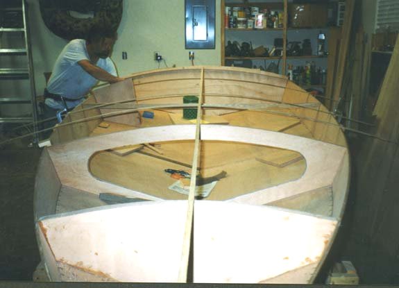
Another modification I made in addition to a taller, more curved deck was using knees. The Scaup plans call for a center cockpit bulkhead that has a cut-out for the cockpit. The Black Brant utilizes two sets of knees. I preferred the knees to the center bulkhead because they separate the side storage areas into three smaller compartments as opposed to two large ones. This seems to be a better configuration for storing decoys. Not wanting to lose the strength the center bulkhead provides to the bottom of the boat, I incorporated timbers with the knees. Future photographs will illustrate these.
Not having knees in the blueprints was no problem. The knees were spaced equally between the storage and motor bracket. Using a bevel gauge I transferred the angle made between the bottom and the side of the boat at the knee locations on the 1/4" Luan and made templates.
With all the bulkheads cut it was time to determine their height and curvature. I must make a very important point at this time. Jeff has a very good feel for how much you can bend plywood. I would not have attempted this modification without his keen sense. The end result was beautiful but could have been disastrous without knowledge of how much you can torture plywood.
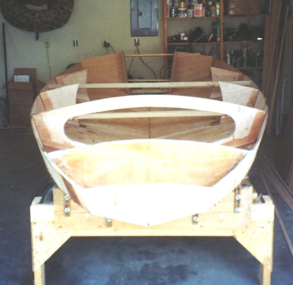
Jeff ripped some 1/4" Luan into 1" strips on his table saw. These were used as battens to determine the proper curvature. Beginning at the front of the boat we clamped on small scrap blocks of wood flush with the tops of the side of the boat. This was done at each bulkhead location. We then clamped or nailed the Luan strips to the blocks with c-clamps and Jeff adjusted the curvature of each Luan strip. He eyed up the curvature and adjusted the Luan battens to both our satisfaction. It was amazing how the Luan battens allowed us to visualize what the decking would eventually look like. To give you an idea of the magnitude of the modification made the storage bulkhead increased in height about 2". I truly believe that this increase in curvature dramatically improved the aesthetics. It also helped when I added a custom gas tank by providing additional clearance.
After the curvature was determined in the front of the boat I placed the flotation bulkhead next to its associated batten and traced the curve. The same was done for the storage bulkhead. Next I cut the tops of the bulkheads along the line of curvature. The storage bulkhead access hole was cut next. I used my cabinet maker's scribe and marked a line 3" inside the perimeter. A coffee can lid was used to round the corners.
After cutting the bulkheads they were planed to take off any flat or rough spots. This would insure a nice joint for the decking.

The next step was to put the flotation and storage bulkhead back in place and continue cutting the tops of the remaining bulkheads. Another batten was laid down the main axis of the boat to eye up the overall height of the boat.

Once all the bulkheads were cut it was time to put a few finishing touches on them. I used a batten and added a curve to the inside of the knees. Sam shows this in his Black Brant and it really looks nice. I also cut out the storage openings in the motor bracket. With my router and a 1/4" round-over bit I routed all edges that would be exposed. This included the storage bulkhead access (inside and out), the curved side of the knees, and the rear storage openings (inside and out). Finally, the motor bracket doubler was laminated with epoxy to the motor bracket. For extra strength I laminated a piece of 3/8" in addition to the 3/4" doubler. I guess the 3/8" is a tripler. At nearly two inches of plywood motor mount strength will never be an issue.
With all the bulkheads complete it was time to prepare for epoxy filleting. Before you begin epoxying the boat together it is essential to make certain the hull is square. This is done both by visual inspection and by taking measurements. For starters I leveled the hull from port to starboard and front to rear. Next, using a tape I measured the distance from each front corner of the bow diagonally to the transom corners. I was fortunate that the distances were equal within 1/16". Had they not been I would have had to have worked and shifted the hull until the distances were the same. The motor well was also checked for squareness in a similar fashion.
Each bulkhead was tacked into place with finishing nails after painting the edges with epoxy. This is needed to seal the end-grain from moisture invasion.

The knees were held into place with fir 1"x2"s to keep them in line with each other. I was now ready to begin the epoxy filleting process.

My friend Jeff Smith gave me a lot of great tips for this portion of the project. Many of the techniques I cover in this section and others are a direct result of him. When I use the word I, you can frequently substitute Jeff for more accuracy.
The plans contain all the dimensions needed to layout the bulkheads. These are cut from 3/4" plywood. The first step before doing any cutting was to spread the hull out according to the dimensions of the bulkheads. Using some 1"x2" Doug Fir and other scrap I cut pieces to the same widths as the bulkheads and tacked them into place with finishing nails.
The first bulkhead cut was the bow. Using the dimensions from the blueprints I penciled the bulkhead on my 3/4" ply and cut it out. To minimize wastage of plywood I laid the bow bulkhead out on the sheet of plywood where the storage bulkhead was to be cut. By placing the bow bulkhead in the center of the storage bulkhead I was using scrap plywood. The center of the storage bulkhead is cut out for access to the storage area. I laid out the storage bulkhead in pencil and made sure I wasn't cutting in the wrong place. I left the top of the bow bulkhead higher than what the plans called for. After reviewing the plans I decided I wanted the decks a little higher with slightly more curvature. Initially all of the bulkheads were cut taller than the plans called for to allow for this modification. After the bow bulkhead was cut I stitched it into place with the bottom and side pieces. I cut another bow bulkhead (slightly smaller) and laminated it to the first after all the filleting process was completed. This was done to provide extra strength where the bow eye would be.
The next component worked on was the transom. Because the Scaup has a motor well the transom consists of two pieces. Once again, using the blueprints I laid out the two pieces on 3/4" plywood. When cutting them out I left the tops higher than the plans called for so more curvature could be added to the decking, as previously mentioned. After they were cut I laid the two pieces on top of each other, clamped them together, and planed the edges to ensure symmetry. The below picture is of the motor well sides but demonstrates how to ensure symmetry. This should be done on all components that are similar.
After they were cut and planed I stitched them into place. Because the motor well divides the transom into two it was necessary to brace them. Using two scrap 1"x3"s and two bar clamps I clamped the two pieces together. By taking measurements from the blueprints and adjusting the clamps the motor well opening was adjusted to match the plans. The 1"x3"s also kept the transom pieces in line with each other.
With the bow bulkhead and the transom in place it was time to move to the internal bulkheads. For the remaining bulkheads I didn't go straight from the plans to the 3/4" plywood. Marine plywood is expensive and mistakes could be costly. Instead I laid out the bulkheads on 1/4" interior Luan, which is very cheap. In order to minimize the amount of Luan used I laid all the bulkheads out on a single sheet. This was accomplished by laying smaller bulkheads out on top of larger ones.
Essentially the Luan was cut into "templates". Beginning with the largest bulkhead I cut out the piece with a jigsaw. Next I dry fitted the 1/4" template in the boat at the appropriate location. Using a block plane the templates were adjusted to the point of a perfect fit. Then the template was laid on the 3/4" Okoume and traced with a pencil. Using a jigsaw I cut out the actual bulkhead. The process was then repeated for the next bulkhead.
The following paragraph was taken from a post on the forum by Jeff Smith. It provides a little more insight into fitting individual bulkheads.
When you lay-out your templates make a strong center line on them & leave it. When you are fitting them, should one side seem to fit better than the other, reverse the template (180 degrees) and see if it is still true. If one side of the template seems to fit both sides of the hull better measure your template to see if it is even (symmetrical). Then when you trace your "fitted" template onto the real plywood use the center line to flip the template and trace the better side for both port and starboard...... carefully. If you have already cut your bulkheads with the real deal wood and they don't fit as nice as you would like, set them the best they will go. Split the difference of any major errors, i.e. the gap at each chine line should be even, a gap along the bottom of the hull should be nearly the same on both sides. Once you get it fitting it's best, tack it in place with small brads leaving the heads out enough to be easily pulled or clamp them in place. Now take a pencil and lay it flat along the bottom and sides of the hull and trace a line on to the bulkhead. Remove the bulk head and look at what it tells you. It should show you if you need to cut or plane a little here or there. You don't need to cut to the line, just think.......if the line is 1/2 the thickness of the pencil at one end and tapers to the edge of the wood at the other, this is the direction you need to go to fit. If you end up taking a little off the bulkhead bottoms and sides, it will just move the fore-bulkheads forward a little. I wouldn't take anything to speak of off the motor bulkhead as the hull is much flatter aft and you don't want the motor positions changed.
The trickiest bulkheads to fit were the motor well components. This is because several components must all come together. I actually worked on the motor well after I had dome some of the fillet work. For continuity it should be discussed here. The motor well components consisted of the motor bracket, longitudinals (motor well sides), and the two transom pieces. With the two transom pieces clamped into place I cut a longitudinal template and planed it until I got a good fit with the bottom pieces and the two transom pieces. I then took the motor bracket and temporarily screwed the bracket doubler (motor mount) to it. The doubler is obtained from the third portion of the transom that was cut away from the other two. With the doubler firmly in place I tacked the motor bracket in its place with finishing nails. Next I took the longitudinal template and fit it between the transom, the motor bracket, and the bottom. This took some adjusting and some planing to get it to fit. It should be noted that the motor bracket needs approximately a 15 degree tilt backwards for proper motor mounting. This is pretty much the industry standard. After I was satisfied with the longitudinal template I traced it on the 3/4" plywood and cut out both longitudinals. The longitudinals were planed for symmetry and tacked into place with finishing nails.
Another modification I made in addition to a taller, more curved deck was using knees. The Scaup plans call for a center cockpit bulkhead that has a cut-out for the cockpit. The Black Brant utilizes two sets of knees. I preferred the knees to the center bulkhead because they separate the side storage areas into three smaller compartments as opposed to two large ones. This seems to be a better configuration for storing decoys. Not wanting to lose the strength the center bulkhead provides to the bottom of the boat, I incorporated timbers with the knees. Future photographs will illustrate these.
Not having knees in the blueprints was no problem. The knees were spaced equally between the storage and motor bracket. Using a bevel gauge I transferred the angle made between the bottom and the side of the boat at the knee locations on the 1/4" Luan and made templates.
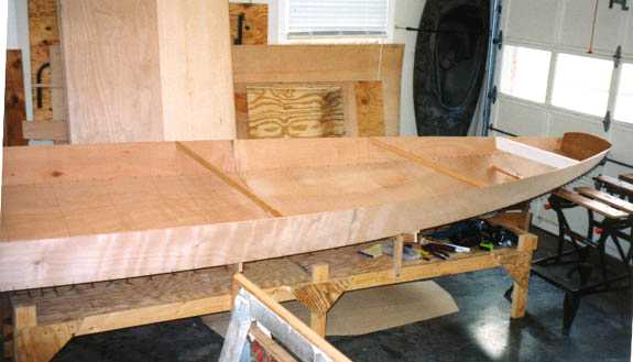
With all the bulkheads cut it was time to determine their height and curvature. I must make a very important point at this time. Jeff has a very good feel for how much you can bend plywood. I would not have attempted this modification without his keen sense. The end result was beautiful but could have been disastrous without knowledge of how much you can torture plywood.
Jeff ripped some 1/4" Luan into 1" strips on his table saw. These were used as battens to determine the proper curvature. Beginning at the front of the boat we clamped on small scrap blocks of wood flush with the tops of the side of the boat. This was done at each bulkhead location. We then clamped or nailed the Luan strips to the blocks with c-clamps and Jeff adjusted the curvature of each Luan strip. He eyed up the curvature and adjusted the Luan battens to both our satisfaction. It was amazing how the Luan battens allowed us to visualize what the decking would eventually look like. To give you an idea of the magnitude of the modification made the storage bulkhead increased in height about 2". I truly believe that this increase in curvature dramatically improved the aesthetics. It also helped when I added a custom gas tank by providing additional clearance.
After the curvature was determined in the front of the boat I placed the flotation bulkhead next to its associated batten and traced the curve. The same was done for the storage bulkhead. Next I cut the tops of the bulkheads along the line of curvature. The storage bulkhead access hole was cut next. I used my cabinet maker's scribe and marked a line 3" inside the perimeter. A coffee can lid was used to round the corners.
After cutting the bulkheads they were planed to take off any flat or rough spots. This would insure a nice joint for the decking.
The next step was to put the flotation and storage bulkhead back in place and continue cutting the tops of the remaining bulkheads. Another batten was laid down the main axis of the boat to eye up the overall height of the boat.
Once all the bulkheads were cut it was time to put a few finishing touches on them. I used a batten and added a curve to the inside of the knees. Sam shows this in his Black Brant and it really looks nice. I also cut out the storage openings in the motor bracket. With my router and a 1/4" round-over bit I routed all edges that would be exposed. This included the storage bulkhead access (inside and out), the curved side of the knees, and the rear storage openings (inside and out). Finally, the motor bracket doubler was laminated with epoxy to the motor bracket. For extra strength I laminated a piece of 3/8" in addition to the 3/4" doubler. I guess the 3/8" is a tripler. At nearly two inches of plywood motor mount strength will never be an issue.
With all the bulkheads complete it was time to prepare for epoxy filleting. Before you begin epoxying the boat together it is essential to make certain the hull is square. This is done both by visual inspection and by taking measurements. For starters I leveled the hull from port to starboard and front to rear. Next, using a tape I measured the distance from each front corner of the bow diagonally to the transom corners. I was fortunate that the distances were equal within 1/16". Had they not been I would have had to have worked and shifted the hull until the distances were the same. The motor well was also checked for squareness in a similar fashion.
Each bulkhead was tacked into place with finishing nails after painting the edges with epoxy. This is needed to seal the end-grain from moisture invasion.
The knees were held into place with fir 1"x2"s to keep them in line with each other. I was now ready to begin the epoxy filleting process.