Steve Sanford
Well-known member
Well, I spent most of the month of March inspecting, measuring, recording, measuring again, and - finally - drawing up plans for the Great South Bay Scooter - the Ted Sanford - that I just restored. If you have been following this long process, you may recall that this vessel was built - in the 1920s or 30s - by Benjamin Hallock in Center Moriches, Long Island. The first Scooter was "invented" on Bellport Bay - which is the eastern end of Great South Bay and is a few miles from Center Moriches.
As usual, I have documented every step of this process and the full account is on my website at:
http://stevenjaysanford.com/great-south-bay-scooter/
This phase begins after Gallery 12. And remember, once you are in a Gallery, click on the first photo so it will enlarge - and then arrow to the right to view it as a slide show with captions. When done in a Gallery, just click the X in the upper left corner.
I started by figuring out how this plank-on-frame boat was put together 90 or so years ago. I imagine anyone building one now would use a newer technology - cedar strip, cold-molding, 'glass composite - but it is fun to appreciate the earlier methods and materials.
Way up forward is the back of the White Oak Breast Hook (Stem?) that holds the bow together and a Whitecedar sawn frame.

The next frames combine bent (steamed) "ribs" for the crowned deck and sawn "Hackmatack knees" for the hull contours. Hackmatack knees are sawn from Tamarack trees where the shallow roots curve outward from the trunk.

Either side of the cockpit, the frames use Hackmatack knees both to frame the hull and to support the side decks.

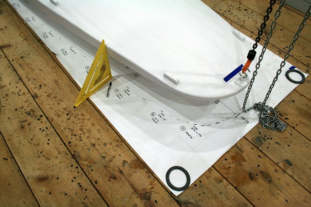
After measuring the locations of each of 15 frames, I leveled the boat both athwartships and lengthwise. I used the sheer - the upper edge of the sides - as a level reference point. I was able to draw the Plan View full-size on the 4' x 17' paper - and recorded many notes there, too.

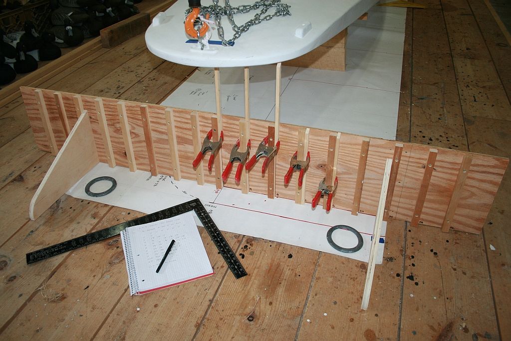
I made this jig to record the "buttock lines" every 4 inches on both the decks and the hull.

I mounted a different set of legs to pick the lines off the hull - measuring up from the floor. All of these curves got recorded as numbers in my notebook.

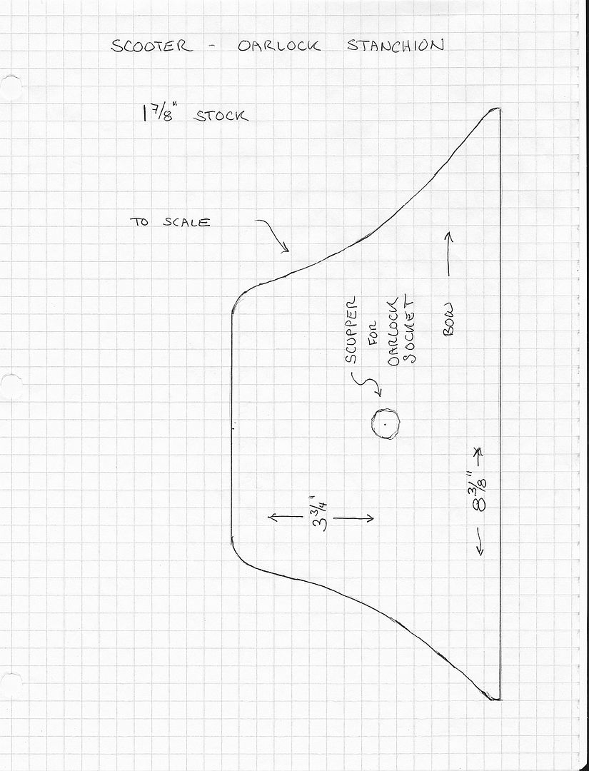
I also measured up and drew special features like the Oarlock Stanchions. Wherever practical, I drew details full-size.

Now all of these numbers got turned back into curves - faired to ignore the bumps and hollows found on most 90-year-olds.

I do not have "real" splines and spline weights, so I improvised with limber battens, notched sticks and spring clamps.

The Plan and Profile views were drawn at 1:8 scale - and were based on my first round of measurements where I used each frame as a station. These are useful as "conceptual overviews" - but more accurate measurements are in the Half-breadths and the full-size the Sections and detail drawings - which are based on stations ever 2 feet along the length.

Here are the Forward Sections. Note how the brass "ice runners" are tipped slightly inward - so they ride on their edges.

Here are the After Sections. The Sheer drops a bit as it approaches the stern.

This detail shows the construction of a typical mid-section frame. Bottom planking is 1/2-inch and the decks are 3/8-inch.

This drawing shows the framing of the Bow (before I replaced the rotted "nose") and of the Fantail Stern. Both are drawn full-size.

Want Plans?
Any ambitious builder could build a Great South Bay Scooter from the information here and on my site. But, if you want to save a couple of days of lofting, full-size copies of these 5 drawings would be very helpful. I am inclined to copy and mail them for cost - I am guessing about $30. Just send me a PM if you are interested. (BTW: These were drawn on 22 x 28 paper. Because it is not one of the standard printer sizes, I am told it would be very difficult to print them from the scan files at precisely the correct dimensions. So, I would have copies made from the originals.)
All the best,
SJS
As usual, I have documented every step of this process and the full account is on my website at:
http://stevenjaysanford.com/great-south-bay-scooter/
This phase begins after Gallery 12. And remember, once you are in a Gallery, click on the first photo so it will enlarge - and then arrow to the right to view it as a slide show with captions. When done in a Gallery, just click the X in the upper left corner.
I started by figuring out how this plank-on-frame boat was put together 90 or so years ago. I imagine anyone building one now would use a newer technology - cedar strip, cold-molding, 'glass composite - but it is fun to appreciate the earlier methods and materials.
Way up forward is the back of the White Oak Breast Hook (Stem?) that holds the bow together and a Whitecedar sawn frame.

The next frames combine bent (steamed) "ribs" for the crowned deck and sawn "Hackmatack knees" for the hull contours. Hackmatack knees are sawn from Tamarack trees where the shallow roots curve outward from the trunk.

Either side of the cockpit, the frames use Hackmatack knees both to frame the hull and to support the side decks.

After measuring the locations of each of 15 frames, I leveled the boat both athwartships and lengthwise. I used the sheer - the upper edge of the sides - as a level reference point. I was able to draw the Plan View full-size on the 4' x 17' paper - and recorded many notes there, too.

I made this jig to record the "buttock lines" every 4 inches on both the decks and the hull.

I mounted a different set of legs to pick the lines off the hull - measuring up from the floor. All of these curves got recorded as numbers in my notebook.

I also measured up and drew special features like the Oarlock Stanchions. Wherever practical, I drew details full-size.

Now all of these numbers got turned back into curves - faired to ignore the bumps and hollows found on most 90-year-olds.

I do not have "real" splines and spline weights, so I improvised with limber battens, notched sticks and spring clamps.

The Plan and Profile views were drawn at 1:8 scale - and were based on my first round of measurements where I used each frame as a station. These are useful as "conceptual overviews" - but more accurate measurements are in the Half-breadths and the full-size the Sections and detail drawings - which are based on stations ever 2 feet along the length.

Here are the Forward Sections. Note how the brass "ice runners" are tipped slightly inward - so they ride on their edges.

Here are the After Sections. The Sheer drops a bit as it approaches the stern.

This detail shows the construction of a typical mid-section frame. Bottom planking is 1/2-inch and the decks are 3/8-inch.

This drawing shows the framing of the Bow (before I replaced the rotted "nose") and of the Fantail Stern. Both are drawn full-size.

Want Plans?
Any ambitious builder could build a Great South Bay Scooter from the information here and on my site. But, if you want to save a couple of days of lofting, full-size copies of these 5 drawings would be very helpful. I am inclined to copy and mail them for cost - I am guessing about $30. Just send me a PM if you are interested. (BTW: These were drawn on 22 x 28 paper. Because it is not one of the standard printer sizes, I am told it would be very difficult to print them from the scan files at precisely the correct dimensions. So, I would have copies made from the originals.)
All the best,
SJS


