Aussie Cackler 14 build

Love scarf cuts. I guess one could do that with a router and template too. But the CNC machine cutting sure is cool.
Awesome! That saved alot of work. Your boss must be one in a million. RM
There are videos online where a handheld router and template was used, but since the machine is here I’d be silly not to utilise it to take care of some of the labour and get a perfect cut as well.

My boss Rob is a qualified cabinet maker who loves woodworking. As a graphic designer and artist, I definitely admire fine woodworking but I don’t really enjoy it or do it because I don’t have the skills or patience to get the results I desire. Rob offered the factory and all tools to help with the build, I think he sees the value in this whole process making me a more skilled employee, but he definitely is a nice bloke as well.
 
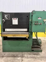
Should be heaps stronger than the butt-fit puzzle scarfs, but not sure if it’s actually stronger than a traditional tapered scarf.
The concept isn’t new, Chase Small Craft do an even fancier version where the visible join line isn’t straight but wavy!
I've used puzzle cuts on a teardrop trailer before, but haven't seen the blind ones used. Thank you for increasing my education!
 
Build progress_3680 copy V2 copy.jpg
For a better perspective here's a plan picture with what I'm constructing marked in pink.

499925584_10236328615539444_7296451570603502475_n.jpg
I’ll be running dual Scepter Marine 25L fuel tanks. I went out and bought one to see how it would fit into the fuel compartment, and where I should place the floatation compartment bulkhead. In the picture the floatation bulkhead looks double thickness, this is only because I had both left and right bulkheads screwed together so I could shape them exactly the same.

498688073_10236328613659397_8673738994345035932_n.jpg
The opening turned out to be too narrow so I grabbed the jigsaw and widened it, then decided to cut again and widen it further. In total it’s now about 30mm (1.2 inches) wider than the original hole from the plans.

497879513_10236328615699448_6987986153172486225_n.jpg
Time to start the hull bottom and side panels. To get them ready for stitching I used a 45° bit in a little Makita trimmer to chamfer all the stitching edges. Had to do it progressively in a few passes because it’s not a powerful router.

498654742_10236328614939429_3085099023622240979_n.jpg
After the chamfers were completed I clamped the panels together and drilled the stitch holes roughly 130mm (5") apart. Also put a bolt through at one corner to act as an axle so that I could pivot the side panel at the chine in order to drill matching holes into the side and bottom sheet.

497432545_10236328613219386_1283514451908102040_n.jpg
Here a the two hull bottoms stitched together. I didn’t know how tight to do the stitching so I left it quite loose -- this was a mistake, should have made them firm.

498448415_10236328616059457_88270288364488754_n.jpg
At the bow the plywood was quite stressed due to the curvature. Had to make the stitches much closer together and still have a bit of an issue of the two sides not joining properly. You can see the wire starting to elongate the stitch holes.

498714757_10236328614099408_5159069519137861186_n.jpg
Once I had the two bottoms stitched together I got excited and threw on the rear transom/motor-mount module to see how it sits!
The green shaded section will be cut out later.

IMG_4103 Coarse putty.jpg
Since you can see the fillets well in the last picture I thought I write a bit of an explanation:
Due to no boat building experience I figured that the fillets for the motor mount module all need to be huge for extra strength. I took the cement/concrete approach -- large fillets need large aggregate, so I raided the CNC's dust extractor and fished out some coarse sawdust. I would have preferred not to have the white melamine and black acrylic chips, but beggars can't be choosers, so into the boat it goes! Also added some fumed silica and small glass chopped strands to the mix.


498582376_10236328616179460_6064158655315037761_n.jpg
Here’s the view from the bow looking back at the roughly placed rear transom/motor-mount module. You can see that the blind puzzle scarf is not so blind at the keel. There was an issue with the CNC's vacuum and the sheet lifted causing the machine to cut too deep. I'll fill the holes with thickened epoxy later.

498622565_10236328613579395_6169490168641466472_n.jpg
I sawed, planned and 80-grit sanded the bottom of the transom/motor-mount module to make it flush fit the hull bottom panels.

498602187_10236328614819426_8182791687249535021_n.jpg
Once the rear transom/motor-mount module fitted nicely, and after trimming a smidge off the left and right transom edges I stitched on both side panels. Once the sides and front transom were fairly well stitched in place I screwed the back edges of the hull bottoms and side panels to the two rear transom panels to lock the back of the boat into place.

498589839_10236328614259412_6409937490224961144_n.jpg
Progress pic of the loosely fitted front transom which needs a heap of stitch tweaking to pull it into place.
 
Last edited:
Matthias,
It is interesting to see first hand how a right-side up build would progress. I have only built upside-down so I am a bit biased. Either way, it gets the job done! The only thing that I would suggest is to get yourself some wood flour. It is super cheap and makes life working with epoxy alot easier. RM
BUILD METHODOLOGY
Would be interesting to see how others approach a right-side-up build. I’m sure there would be different approaches taken by different builders. There were quite a few times that I wished I had built upside down, but due to lack of space at my workplace there was no room where I could set up permanently and build. The rough plan was to get some structural integrity to the hull as quickly as possible to enable it to be hoisted to the ceiling, out of the way when necessary. The hull, plus build frame hoisted to the ceiling would have been too bulky. A different option would have been to put the build frame onto a dolly, then wheel it outside into the car park and store it there under a tarp when I wasn’t building, but didn’t like that idea.

WOOD FLOUR
As far as I can tell, building plywood boats here in Australia these days is a fairly niche activity. Most home builds are aluminium kit boats. Wood flour is something that I could not find a local supplier of, and I wasn't prepared to ship it in from the USA. Depending on jobs, our work CNC router produces bags of fine wood dust, all the way through to coarse chips/sawdust so I figured that would be good enough, and I could choose the grade depending on what I thought the build needed.
Most of the fillets ended up being roughly 40% fine dust with 60% fumed silica. That gave me a fairly creamy mix. The very coarse fillets on the motor mount module were all faired over with a layer of smooth mix later on.
 
Matthias

I am really enjoying following this build. When I compare my first to yours there is a lot of similarity in approach, but you also have modern tools I never dreamed of. Your build illustrates how stitch and glue has evolved over the years.

You are past this part now but I'll mention it anyway. The angle on a dovetail router bit is a nice match to the angle of the chine. You mentioned using a 45 degree chamfer bit. With a dovetail bit and short fence on my router I cut the chine edge on the bottom pieces. I think mating the bottom and sides was easier to do since the angle was pretty close to perfect at the start. For the keel I did use a 45 degree chamfer bit.

For wood flour a really good source of very fine dust is that created by a Timesaver belt saver. Note sure if you have Timesavers in Australia but these are big, say 36-42" wide belt sanders used in cabinet shops to sand face frames and table top glue ups. They make a ton of dust and it is very fine and makes a fillet that is smooth and easier to work with. I can't imagine a cabinet shop not being happy to give you dust collected from one of these machines. They have to do something with it. I bet your boss Rob knows a shop nearby that has one.

Keep up the good work!
 

Attachments

  • TimeSaver.webp
    TimeSaver.webp
    157.3 KB · Views: 1
Last edited:
One more thought. After you cut out the motor well bottom and before you get too far down the road mount your motor to the transom and check clearances. I think you will be okay on the sponsor bottom corners but you might find interference somewhere else depending upon your motor. Some of the new four strokes have thick midbodies that can hit the sides of the motor well at the top. Also some controls or the tiller could interfere with the splash well. When I recently retrofit my Black Brant with a splash well I put the motor on mid project and it really helped me see problem areas and avoid mistakes.
 

Attachments

  • IMG_6009.JPG
    IMG_6009.JPG
    266.6 KB · Views: 14
  • IMG_6164.JPG
    IMG_6164.JPG
    223.4 KB · Views: 13
  • Img_6237.jpg
    Img_6237.jpg
    267.4 KB · Views: 14
You are past this part now but I'll mention it anyway. The angle on a dovetail router bit is a nice match to the angle of the chine. You mentioned using a 45 degree chamfer bit. With a dovetail bit and short fence on my router I cut the chine edge on the bottom pieces. I think mating the bottom and sides was easier to do since the angle was pretty close to perfect at the start. For the keel I did use a 45 degree chamfer bit.
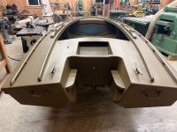
I was somewhat conflicted when I started to prepare for the stitching process. The cabinet maker in Rob tried to convince me to make all panels as close to flush fit as possible. I did not like that idea for two reasons.
1/ it sounded like a lot of work ( but I would have become quite proficient with the plane and sander)
2/ it contradicted info published in Devlin’s Stitch and Glue Guide that is supplied with his plans. (Bad photo of computer screen attached)

I decided to follow the Devlin illustration/process and actually cut all the boat’s mating edges at 45°.
A lot of YouTube I watched about the stitch and glue process mentioned that a somewhat loose fit is a good fit, and I must say that I have embraced, and enjoyed, that throughout my build. My thinking is, “I want to build a boat, I don’t want to learn how to be an accomplished joiner”.

PS. Glad you are enjoying the posts. It’s definitely interesting to see how differently people build their boats. I wish I’d found this forum earlier, a lot of questions that I had to take a punt on and figure out for myself would have been answered here.
 

Attachments

  • IMG_8589.jpeg
    IMG_8589.jpeg
    629.6 KB · Views: 8
Last edited:
One more thought. After you cut out the motor well bottom and before you get too far down the road mount your motor to the transom and check clearances. I think you will be okay on the sponsor bottom corners but you might find interference somewhere else depending upon your motor. Some of the new four strokes have thick midbodies that can hit the sides of the motor well at the top. Also some controls or the tiller could interfere with the splash well. When I recently retrofit my Black Brant with a splash well I put the motor on mid project and it really helped me see problem areas and avoid mistakes.
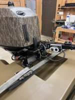
Stay tuned, I need to get my build thread up to date because that’s what I worked on today!
Without giving too much away, I do have some minor issues…

D0339814-2BBA-4CA2-B133-BF22D3D7F009.jpeg
Thanks for publishing your pics.
Even though I hate sanding, the finish on your boat looks fantastic and reckon I could be inspired to sand mine just a bit more!
What is the purpose of the circled pieces?
 
Matthias

Those keep water from climbing the inside walls of the sponsons. They also limit the last little bit of travel of the motor at full turn and hitting the corners I clipped.

On the fitting of panels discussion. I was bothered by the little edge created when chamfering both the bottom and side pieces and how finicky it could be getting the panels properly positioned with such a small contact area. My method of a dovetail bit cut made that alignment activity trivial.
 
Yep, that was a downside of the 45° chamfer. The join line at the chine did wander in places and there were areas where I had to use the wooden mallet to persuade it back. One section wouldn’t go and I needed to insert a chisel to lever the panels into place. Overall if I had to give the joins a score I reckon I’d give them 80 out of 100, pretty good but not perfect.
 
Matthias,
Although I wholeheartedly agree with your decision to use 1/2"(12mm) plywood, I'm sure it contributed to the difficulties in stitching it together compared to 9mm.
In an earlier post you mentioned that for this boat you used construction industry structural ply. The quality looks amazing compared to what is available in the United States.
RM
 
Last edited:
Matthias,
Although I wholeheartedly agree with your decision to use 1/2"(12mm) plywood, I'm sure it contributed to the difficulties in stitching it together compared to 9mm.
In an earlier post you mentioned that for this boat you used construction industry structural ply. The quality looks amazing compared to what is available in the United States.
RM
The structural ply is CD quality. If you have a look at the picture of the front transom in the process of being stitched, that shows a D side: there are a couple of open knots and quite coarse grain. It’s not visible in that pic but some of the open knots and voids were filled with a chalky filler. You can get hardwood (eucalyptus) or softwood (Radiata Pine) options, I went with the softwood because it was lighter.
I’m not building an ocean going yacht, just a river and estuary explorer, so in my mind the structural ply is good enough, especially once its completely sealed with epoxy and glass.

I did also use some marine ply in the boat. The floorboards and bow deck are 12mm BB quality, medium-light hardwood marine ply from Malaysia. The floorboards for the fuel compartments are 6mm mixed hardwood (eucalyptus) marine ply. And then I really lashed out and bought one sheet of 6mm Gaboon marine ply for the anchor well. I wanted the cheaper mixed hardwood 6mm ply, but it was all out of stock, so had no choice but to buy the premium Gaboon.
 
01 Bow clamp.jpg
I tried a few times to close the gap at the keel line by twisting the wires tighter to no avail. The wire was too brittle and kept snapping so it was time to screw in some blocks and clamp the gap shut.
02 Bow stitches.jpg
The keel line gap is now tightly closed and the bottom point of the front transom fits just about perfectly and lines up along the centre line.

03 Bow transome stitched.jpg
Front transom now also looks nice. There is still a gap above the chine, but it's even on both sides so I'm not concerned about it. The transom also doesn't align properly to the sides along the top edge -- it's sitting a bit low, but again, it's even on both sides. My main concern is keeping the boat symmetrical, so I'm happy to leave it and fix it later with some creative sanding and planing when I install the deck.

04 Bulkhead install.jpg
I then marked the position of the bulkheads, drilled screw holes, and screwed the bulkheads into place from beneath the boat. Since i was working alone this was a bit tricky and I had to support the bulkhead panels with temporary steel angle brackets.

05 Bulks done.jpg
A few hours later and its all done.The camera angle makes this pic of the boat look very strange -- don't be concerned, I am indeed building a Cackler 14, not a wooden bathtub!
😅


All bulkheads have been screwed into place. I did not follow the plans for the exact placement of the bulkheads. They are kinda close, but I installed them where they gave the best flush fit to the hull panels making sure the sides kept a nice smooth curve. As the bulkheads were installed I kept measuring the boat diagonally corner to corner to make sure it wasn't racked. To my surprise I was only 3mm out after the last bulkhead was fastened so I thought I should lock it in place and epoxy the front transom and bulk no.1

06 My flower.jpg
Since I'm now starting to epoxy in earnest I'll mention the making of the glue again...

I raided the filter unit of our CNC machine's dust extractor and retrieved some very fine wood dust. It's not wood flour, but it's free and I see no reason not to use it as a thickener to make the epoxy paste for the filleting process.

07 Biaxial.jpg
Concerned that small thickened epoxy fillets between the wires wouldn't suffice at holding the front transom in place after I remove the clamp, I cut some strips off the roll of 400gsm biaxial tape to epoxy between the wires for extra strength.

08 Bow glue schedule.jpg
Wow, this looks messy! First i mixed a batch of thinned epoxy and painted all the joins to pre-soak the plywood. I then added roughly half wood dust, half fumed silica to the leftover epoxy to make a paste for filleting the gaps. Another batch of liquid epoxy was mixed and the glass tape was laid in place. The green lines show roughly where I placed the glass.

09 Bow glued.jpg
Doesn't look great, but hopefully after I remove the wires, add more fillets, another two layers of tape and paint the whole compartment with epoxy it will look better. Not that it really matters because most of these surfaces will never be seen.

10 Bow transom misaligned.jpg
I filled in some of the outside gaps with the special epoxy chocolate!
Green circle shows a better view of the transom misalignment, but the other side is exactly the same so I reckon it'll be alright on the night!

11 Nice curves.jpg
The sides of the boat have a good uniform curve without any wonky bits, so I'm a happy camper. Hopefully when I flip the boat over, the underside will look just as nice -- fingers crossed!
 
Back
Top