You are using an out of date browser. It may not display this or other websites correctly.
You should upgrade or use an alternative browser.
You should upgrade or use an alternative browser.
Question For Dave McCann and Any Other Machinist
- Thread starter Eric Patterson
- Start date


Richard Lathrop
Well-known member
What is the final turned diameter? Tangental cut means 1 7/8" minus diameter to get height of the cutting edge of tool above cross slide deck?
Rick
Rick
Richard
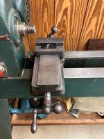
Final dia. about 1 1/2" - 1 3/4". There's enough room. But you can see why in the original picture why they had the tooling flat on the cross slide.
Final dia. about 1 1/2" - 1 3/4". There's enough room. But you can see why in the original picture why they had the tooling flat on the cross slide.
Huntindave McCann
Well-known member
EricRichard
Final dia. about 1 1/2" - 1 3/4". There's enough room. But you can see why in the original picture why they had the tooling flat on the cross slide.
What width would you need the tool steel to be to cut the profile? Wider than the 4 inch width of the cross slide deck?
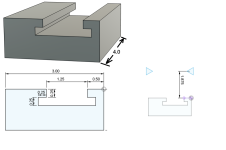
(A) Thickness of the tool steel profile cutter:
Given the 1.875 distance from the deck to lathe centerline, minus a radius of .875 (workpiece diameter of 1.750) leaves 1.00 inch minimum thickness for the tool steel. This should provide plenty of strength to the cutter.
(B) Clamping lugs:
How accurate are the Tee slot dimensions I have shown (1/4 by 1/4 by 1/4)?
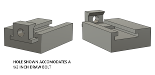
Assuming a height above the deck to the top of the clamping lugs to be .625 should provide adequate material for a draw bolt hole. The lugs could very well be made taller ( and probably should be) to accommodate more tool steel material under the clamping bevel. Not sure just where the best height would be, while still keeping the lug as low as possible to avoid any interference. Not sure if interference would even be an issue, as I would not expect the clamping lug to ever get to the point of tangency with the workpiece.
These again are just rough sketches. I'm not a designer or mechanical engineer, I just build the stuff.
Attachments
Last edited:
Dave
You have almost enough info there to satisfy a machine shop. You have done this before . In all seriousness I am most thankful for your help.
I'm off today and am at the shop taking measurements. I cannot ever see cutter width exceeding 4" and 3"- 3 1/2" will be the norm. Also the largest finished diameter will be under 1 5/8" and typically 1 1/2". The smallest diameter is 5/8" if I make inserts by knife. If I just make barrels then 7/8".
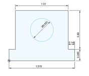
Your "T" dimensions are close. I have a t-nut in my hands. The bottom wider portion is .265 thick and 1.515" wide. The top portion is .225 thick and 1.22" wide. If you change these dimensions and show the side with the angle portion I think the clamp design is good to go.
I'm in discussion with a tooling company about the cutter. I may call you with a few questions about that. Thanks!
You have almost enough info there to satisfy a machine shop. You have done this before
. In all seriousness I am most thankful for your help.I'm off today and am at the shop taking measurements. I cannot ever see cutter width exceeding 4" and 3"- 3 1/2" will be the norm. Also the largest finished diameter will be under 1 5/8" and typically 1 1/2". The smallest diameter is 5/8" if I make inserts by knife. If I just make barrels then 7/8".
Your "T" dimensions are close. I have a t-nut in my hands. The bottom wider portion is .265 thick and 1.515" wide. The top portion is .225 thick and 1.22" wide. If you change these dimensions and show the side with the angle portion I think the clamp design is good to go.
I'm in discussion with a tooling company about the cutter. I may call you with a few questions about that. Thanks!
Last edited:
Huntindave McCann
Well-known member
Eric,
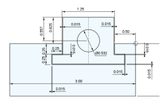
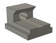
I really don't know my way around the design program but here is what I have. It looks a bit different because I have left more material in the Tee slot area. I believe I have provided all the info needed to build the clamp prototype.
I will work on the dimensions for the clamp bevel cut into the tool steel.
I would suggest you build a wood model of both the tool steel and the clamps, to prove out the dimensions when I get the rest to you.
Attachments

Dave
If you don't know your way around the design program you've done a great job of convincing me otherwise. I take it you did these with the free version of Fusion 360 you've mentioned in the past.
We are on the same wavelength. I am going to make wood prototypes. Quick question. Why the .531 bore for a 1/2" bolt?
Thanks again for all your help.
Huntindave McCann
Well-known member
Just general machine clearance for bolt holes. 32nd of an inch is common for the thru hole. Actually a 1/2 inch bolt may be overkill. 3/8 might be sufficient.Quick question. Why the .531 bore for a 1/2" bolt?
Yes, using the free version of Fusion. My learned skill set is lacking for what I'm trying to accomplish. Took me several tries to generate those and I'm pretty sure I went the long way around the block. Sometimes I do something and then don't understand what exactly I did to accomplish it and even more, how do I change it.
Huntindave McCann
Well-known member
Eric,our "T" dimensions are close. I have a t-nut in my hands.
Would like to know this dimension on the cross slide. It is going to be thicker than the tee nut thickness you stated. "The top portion is .225 thick and 1.22" wide."

It is otherwise the t-nuts would be ineffective at locking onto the cross slide. I'm headed to the shop in a bit to load up the boat before I go hunting this afternoon. I'll post that dimension.
Dave
That measures .220. Turns out the t-nut that just came in the mail is a tad proud.
That measures .220. Turns out the t-nut that just came in the mail is a tad proud.
Huntindave McCann
Well-known member
Eric,
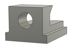
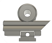
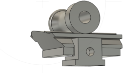
This is just the model, dimensions would be on the sketch's.
The wooden work piece as drawn is 1.625 max dia. with a .625 dia. thru bore and a length of 3.25 inches.
The lathe centerline distance to the cross slide deck is 1.875
The stack up is as follows;
cross slide deck
shim pack (not shown except as a slight gap) (drawn diameter is based ion .015 shim pack.) Shims removed increases work piece diameter up to .030 max. Shims could be added to decrease the work diameter. 0.000 shim to max of .030 shim, to give you .060 range of dia. adjustment
.375 spacer block
Tool steel height to top of clamp cutout = .484
Tool steel height to lowest edge of clamp cutout= .160
Tool steel height above the clamp opening, governed by workpiece profile.
Overall thickness of tool steel = 1.441 (smaller diameter work piece would require thicker tool steel)
I have shown excess length for the tool steel, not sure what you require from the center of the tee slot to to cutting edge or to the back end of the tool steel.
Also not sure what cutting edge angle is needed. I have shown a 45 degree bevel to the cutting edge.
The actual cross slide deck is not shown. Obviously only one of the two needed clamps, is shown.
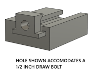
The draw bolt hole shown, accommodates a .375 diam. draw bolt, which clears the bottom of the tool steel. (without any need for a relief cut)
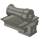
This is just the model, dimensions would be on the sketch's.
The wooden work piece as drawn is 1.625 max dia. with a .625 dia. thru bore and a length of 3.25 inches.
The lathe centerline distance to the cross slide deck is 1.875
The stack up is as follows;
cross slide deck
shim pack (not shown except as a slight gap) (drawn diameter is based ion .015 shim pack.) Shims removed increases work piece diameter up to .030 max. Shims could be added to decrease the work diameter. 0.000 shim to max of .030 shim, to give you .060 range of dia. adjustment
.375 spacer block
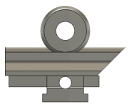
Tool steel height to top of clamp cutout = .484
Tool steel height to lowest edge of clamp cutout= .160
Tool steel height above the clamp opening, governed by workpiece profile.
Overall thickness of tool steel = 1.441 (smaller diameter work piece would require thicker tool steel)
I have shown excess length for the tool steel, not sure what you require from the center of the tee slot to to cutting edge or to the back end of the tool steel.
Also not sure what cutting edge angle is needed. I have shown a 45 degree bevel to the cutting edge.
The actual cross slide deck is not shown. Obviously only one of the two needed clamps, is shown.
The draw bolt hole shown, accommodates a .375 diam. draw bolt, which clears the bottom of the tool steel. (without any need for a relief cut)
Attachments
Last edited:
Huntindave McCann
Well-known member
I want a shearing cut for an acceptable finish.
This is why I mentioned the bevel angle you wish to have ground onto your tool steel.a flat knife ground to profile scrapes. I've never had luck scraping profiles more than about 1/2" wide.
A standard lathe scraper held in the normal manner has a zero degree rake. The cutting face is 90 degrees to the work as it passes the cutting edge.
The "tangential" cutter you propose to use is subject to the same "rake" angle forces. A "negative rake" pushes the chip back into the workpiece. When cutting with wood, "negative rake" is never good. Even "zero degree rake" is not the best, as you state, "scraping" can produce chatter and tear out.
"Positive rake" lifts the chip away from the work piece (think of a hand plane curling the chip upward) Even more so when the plane is canted producing a shearing action along with this positive rake.
==================
On a rotating workpiece, with the tool entering along a horizontal path, the "zero degree" point in reference to the cutting face changes as the diameter changes. A tool height producing a .875 finished diameter needs a much more acute bevel to cleanly cut at the 2.00 inch diameter than it does at a 1.125 inch diameter.
It the tool has a 45 degree bevel, it will cut like crap and require greater force to cut (might not cut at all) on a 2 inch rough diameter.
Given the same 45 degree tool bevel and a rough diameter of 1.125 inches, the tool should cut smooth and clean all the way down to the finish diameter of .875 inch.
The take away; Grind the tool with a 45 degree bevel , rough cut (precut) your stock to within .250 diameter of finish dimensions.
Attachments


Last edited:
Dave
I'm at the shop now and will tKe a much closer look tonight or tomorrow. One thing that isn't making sense at first glance is the 3/8" spacer block. Is it actually left and right blocks with the 3/8" draw bolt separating them? Looks like all occupy the same space.
I'm at the shop now and will tKe a much closer look tonight or tomorrow. One thing that isn't making sense at first glance is the 3/8" spacer block. Is it actually left and right blocks with the 3/8" draw bolt separating them? Looks like all occupy the same space.
Huntindave McCann
Well-known member
Yes, not enough available room to have the two pieces connected. I spaced them apart the same distance as the tee slot opening.One thing that isn't making sense at first glance is the 3/8" spacer block. Is it actually left and right blocks with the 3/8" draw bolt separating them?
Attachments
Huntindave McCann
Well-known member
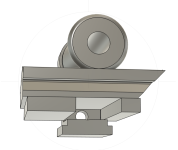
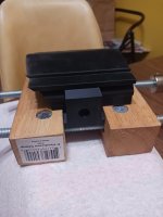
Prototype pieces are in the mail. 
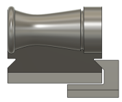
Cutter block profile shown, is from a goose call barrel I had on hand. Clamp groove dimensions would always remain the same. Only the top profile would change, per your design.


Cutter block profile shown, is from a goose call barrel I had on hand. Clamp groove dimensions would always remain the same. Only the top profile would change, per your design.
Attachments


Last edited:
Dave
Below are just a few of the YT videos I found that show a similar set-up to what we've been discussing. They all use more sophisticated lathes than mine but they are also tens of thousands of dollars and capable of making thousands of units a week. Far more capacity than I'll ever have use for. But the meat of the system, tool and tool holder, are transferable and give a level of consistency otherwise not attainable.
Below are just a few of the YT videos I found that show a similar set-up to what we've been discussing. They all use more sophisticated lathes than mine but they are also tens of thousands of dollars and capable of making thousands of units a week. Far more capacity than I'll ever have use for. But the meat of the system, tool and tool holder, are transferable and give a level of consistency otherwise not attainable.
Huntindave McCann
Well-known member
Eric,Any thoughts on this, or other ideas on how to attach the milled-to-pattern cutter to the cross slide? Maybe the simplest and easiest means is to counterbore the cutter and use a bolt and T-nut to lock it in place.
I drew up the clamping system, purely based on duplicating what was shown in the original photo. Mulling it over, I believe that it NOT the best choice. My computer mouse died and I am presently handicapped in using my Fusion software. Tomorrow or the next day I'll get something drawn up in a new direction.
On another note; Estimated delivery of your package is Friday, the 23rd.
Dave
I look forward to your alternative ideas.
I look forward to your alternative ideas.