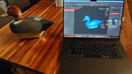
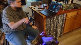
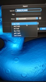
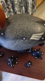
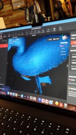
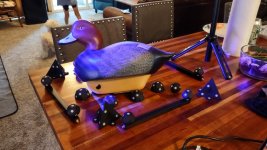
The use of a scanner came up in which I posted about my experience with a scanner. Then today my son comes over with a new toy. I thought you guys might be interested. This is our first attempt with Kyle's new scanner with a lot to learn but it was a fun afternoon of trial and error. Our subject was a decoy Yukon Mike carved for me as an urn for my Lab Gus we lost in 2008. It started with making several scans of different parts of the decoy and stitching the scans together. Black portions of the decoy was the toughest so targets attached to the decoy helped to scan the areas. Those were target dots. There are a few shown in the picture. Ultimately we ended up using like 50 to 75 targets. The detail the scanner picks up is impressive as you can see the feather detail Mike put into the decoy if you zoom into the scan in blue. The yellow screen shot is where the several scans are being stitched together. Steve brought up the use of a 3d printer. 3d printers require a .STL file to generate a finished model. One of the file extensions is a .STL file. Next step is to add a 4 axis system to Kyles CNC wood router. Eventually once we know how to use it better, I have a boat in mind to scan from a well known local scull boat builder.
You are using an out of date browser. It may not display this or other websites correctly.
You should upgrade or use an alternative browser.
You should upgrade or use an alternative browser.
Revisiting Steve Sanford's post on lofting boat lines.
- Thread starter Ed L.
- Start date
very cool!
RM Anderson
Well-known member
I worked for a short time for Case New Holland as a Quality Control Inspector and used Coordinate Measuring Machines in the course of my work. Out of curiosity, what are you using for your datum? RM
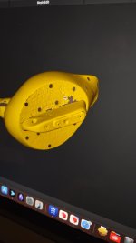
We started with the hole in the keel as our base data point. Not real datums in the sense of xyz coordinates. In the photo we placed data markers on a flat surface to establish a horizontal plane to the base of the decoy. After that it was trial and error to determine how many data features were needed on the body of the decoy and why we had several scans that needed to be stitched together. You can see in the yellow photo the number of data points stickers that were on the bottom alone. The software will delete those if you want. They can remain if the model will be used for say mold making either as gates or ejector pins. This many of course would not be used.I worked for a short time for Case New Holland as a Quality Control Inspector and used Coordinate Measuring Machines in the course of my work. Out of curiosity, what are you using for your datum? RM
His scanner is a Revopoint scanner which captures data as point cloud then the software stitches the data into a polygon mesh to create the surfacing. In the end there were over 4 million polygons. It's amazing what can be done on a laptop today.
Attachments

Last edited: