
After the U-bolt: The next steps in the Model 26

Steve Sanford

Well-known member
All~
My earlier U-bolt post was an early step in the vessel I am building for the Tuckerton Show in late-September.
44th Old Time Barnegat Bay Decoy and Gunning Show - September 26 & 27
https://www.co.ocean.nj.us/cultural....aspx?ID=2e868c92-9761-4606-95c5-c3ea2650601a

As I intend this boat to be a bit of a surprise, I will not be divulging here the entire, step-by-step process until after the Show. So, I will be depicting only portions of the build without the overall context. In this post, I am beginning the internal framing by fabricating and installing blocks at both ends of the hull to hold the midline framing member of the decks.

You may know that I commonly serve in the role of Commodore Stickler Fussbudget when it comes to boat terminology - self-appointed (and uncompensated) Keeper of the Language. So, I am a bit embarrassed and stumped when trying to give the right name to the central longitudinal framing member above the rails, i.e., for the decks. Whereas conventionally planked decks do not need a central framing member, they often use a heavy (thicker) plank known as the King Plank in this location. This supports deck hardware and may also serve as a support for the other deck planks. In any event, the first step in laying out the framing - bulkheads, purlins, carlins, et cetera - once the hull itself is done is to establish the centerline by fastening a full-length board from stem to stern. In this post I am showing my work only at the stem and stern. The hull is a production 'glass hull that I have stripped down as I convert it to a gunning boat. Without bigger "context" photos, I ask you to bear with me. I will focus on the "trees" without showing you the "forest".

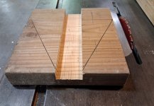
Here is the first step - laying the central frame on some heavy stock from which blocks will be fitted both forward and aft. I am using treated Southern Yellow Pine (SYP) - 2x8. Note the grain running athwartships to avoid splitting. I plowed the dado on the table saw with standard blade - to save the time needed for a dado blade/set and because the rough surface will help the 3M 5200 bedding that I will use as permanent fastening.

sm 2 Model 26 - Bow and Stern blocks - dado.jpg

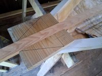
The central frame - which one source called a "central stringer" (but a stringer is down inside the hull in my experience and not part of the deck) - is 3/4" x 2" untreated SYP that I planed down. It once was part of the bleachers in the Cambridge Central School gym.... I am trying to make this boat as light as possible so avoided a denser wood.
sm 1 Model 26 - Bow Block with midrib.jpg

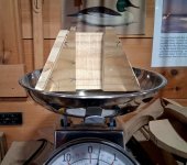
Lots of careful steps in fitting the bow block to the hull and deck "rim" (the latter left as a "shelf" to receive deck fasteners later in the build). This is NOT a conventional breast hook because it does not serve to tie the stem and gunwales together. It will add 5 ounces to the boat.
sm 3 Model 26 - bow block 5 oz 1.jpg

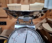
The stern block was cut from the same 2x8 - with the same dado. It, too, weighed in at 5 ounces.
sm 4 Model 26 - Stern Block 5 oz 1.jpg

Both blocks are glued in with thickened epoxy. I added: milled fibers, 1/4-inch 'glass fibers, and some fairing compound. The first 2 ingredients add structural strength, the third just stiffens the mixture to prevent oozing and running during the cure. It is the colloidal silica in the fairing compound that provides the stiffening.
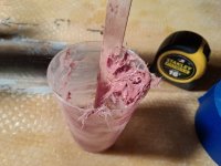
sm 5 Model 26 - Epoxy + MF + FC + fibers.jpg

The stern block was clamped once I was certain that it was dead center - hence the measuring tape. The masking tape, of course, prevents the frame from sticking; it is not ready to be fastened permanently.
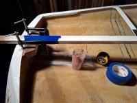
sm 6 Model 26 - Stern Block - glued and clamped.jpg

The excess epoxy mix is wiped below. Note how the block is proud of the existing deck. It will be faired to the deck contour later in the process.
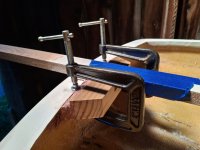
sm 7 Model 26 - Stern Block clamped CLOSEUP.jpg

The bow block was self-centering. The clamping force here needed to be upward - to seat the rabbets on both upper edges of the block.
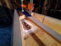
sm 8 Model 26 - Bow Block - glued and clamped.jpg

Progress will be slow (LOTS of family obligations) - but still plenty of time before Tuckerton.

All the best,

SJS

 
Steve, do you have a book or something that defines the terminology and has illustrations? If not do you have plans to make one?
 
Steve, do you have a book or something that defines the terminology and has illustrations? If not do you have plans to make one?
Ben~
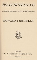
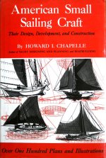
As you might imagine, have LOTS of books on building boats - ANd I had a Dad who understood the importance of correct terminology (in just about any topic....) But, I will recommend two to anyone who enjoys this site - or otherwise "messes about in boats":
Howard Chapelle worked for this Smithsonian. He spent many years finding traditional vessels in boatyards and shipyards around America - but especially along the Atlantic Tidewater - and measuring and otherwise documenting them for posterity. ( https://en.wikipedia.org/wiki/Howard_I._Chapelle)


He published several books - and many plans (available from the Smithsonian). This volume includes all of the standard terminology with suitable line drawings. It is the best foundation for the world of traditional boats (IMO).
sm BOAT BUILDING - Title page.jpg
Zack Taylor was the Boating Editor for Sports Afield when I was growing up. This book includes numerous plans and building instructions for gunning vessels. I re-read it every few years - and post sections here on duckboats.net whenever I see the need. Best of all, he treats the reader as a competent amateur who can apply himself/herself to the joyous realm of building one's own boat from scratch. Lots of other grand thoughts on coastal gunning as well.
Successful Waterfowling - Zack Taylor cover.jpg
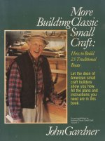
I will add one more. John Gardner's books (I have Volume 1 and 2 but think there might be a 3rd that includes both). They describe how to build small traditional boats - and respect the conventions of terminology. It is worth reading his CV on Wikipedia: https://en.wikipedia.org/wiki/John_Gardner_(boat_builder)

sm 1 John Gardiner - More Building Classic Small Craft - COVER.jpg

There are other very good books that explain other building methods (strip-building, cold-molding, stitch-and-glue) - but I recommend building a sound foundation of knowledge first (yes, I am resolutely Old School!).
Hope this helps!

SJS
 
Last edited:
All~
My earlier U-bolt post was an early step in the vessel I am building for the Tuckerton Show in late-September.
44th Old Time Barnegat Bay Decoy and Gunning Show - September 26 & 27
https://www.co.ocean.nj.us/cultural....aspx?ID=2e868c92-9761-4606-95c5-c3ea2650601a

As I intend this boat to be a bit of a surprise, I will not be divulging here the entire, step-by-step process until after the Show. So, I will be depicting only portions of the build without the overall context. In this post, I am beginning the internal framing by fabricating and installing blocks at both ends of the hull to hold the midline framing member of the decks.

You may know that I commonly serve in the role of Commodore Stickler Fussbudget when it comes to boat terminology - self-appointed (and uncompensated) Keeper of the Language. So, I am a bit embarrassed and stumped when trying to give the right name to the central longitudinal framing member above the rails, i.e., for the decks. Whereas conventionally planked decks do not need a central framing member, they often use a heavy (thicker) plank known as the King Plank in this location. This supports deck hardware and may also serve as a support for the other deck planks. In any event, the first step in laying out the framing - bulkheads, purlins, carlins, et cetera - once the hull itself is done is to establish the centerline by fastening a full-length board from stem to stern. In this post I am showing my work only at the stem and stern. The hull is a production 'glass hull that I have stripped down as I convert it to a gunning boat. Without bigger "context" photos, I ask you to bear with me. I will focus on the "trees" without showing you the "forest".

Here is the first step - laying the central frame on some heavy stock from which blocks will be fitted both forward and aft. I am using treated Southern Yellow Pine (SYP) - 2x8. Note the grain running athwartships to avoid splitting. I plowed the dado on the table saw with standard blade - to save the time needed for a dado blade/set and because the rough surface will help the 3M 5200 bedding that I will use as permanent fastening.


View attachment 77814

The central frame - which one source called a "central stringer" (but a stringer is down inside the hull in my experience and not part of the deck) - is 3/4" x 2" untreated SYP that I planed down. It once was part of the bleachers in the Cambridge Central School gym.... I am trying to make this boat as light as possible so avoided a denser wood.

View attachment 77813

Lots of careful steps in fitting the bow block to the hull and deck "rim" (the latter left as a "shelf" to receive deck fasteners later in the build). This is NOT a conventional breast hook because it does not serve to tie the stem and gunwales together. It will add 5 ounces to the boat.

View attachment 77815

The stern block was cut from the same 2x8 - with the same dado. It, too, weighed in at 5 ounces.

View attachment 77816

Both blocks are glued in with thickened epoxy. I added: milled fibers, 1/4-inch 'glass fibers, and some fairing compound. The first 2 ingredients add structural strength, the third just stiffens the mixture to prevent oozing and running during the cure. It is the colloidal silica in the fairing compound that provides the stiffening.

View attachment 77817

The stern block was clamped once I was certain that it was dead center - hence the measuring tape. The masking tape, of course, prevents the frame from sticking; it is not ready to be fastened permanently.

View attachment 77819

The excess epoxy mix is wiped below. Note how the block is proud of the existing deck. It will be faired to the deck contour later in the process.

View attachment 77818

The bow block was self-centering. The clamping force here needed to be upward - to seat the rabbets on both upper edges of the block.

View attachment 77820

Progress will be slow (LOTS of family obligations) - but still plenty of time before Tuckerton.

All the best,

SJS
Nice work Steve.
 
Good morning, All~

A bit more progress on the Top Secret Model 26. Little time available as we moved my Mom here for August and September - Family First every day....

I am now making the frames - which will be a total of 4. Once installed, they will establish the overall shape of the vessel - and it will really start to look like a Proper Boat.

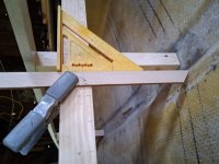
The "king plank" (see earlier thoughts....) establishes the profile of the decks. It is propped up with struts along its length.

sm 10 Model 26 - Middle Frame - strut and level.jpg

Each strut is temporary. Both the king plank and each frame are screwed to each.

sm 11 Model 26 - Middle Frame - notch and strut detail.jpg

Each is set plumb. the yellow duct tape will prevent epoxy from sticking where it shouldn't stick.

sm 10 Model 26 - Middle Frame - strut and level.jpg

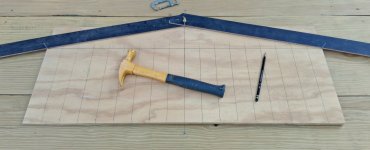
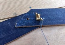
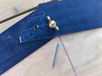
I am using 1/2-inch AC plywood for the frames. LOTS of careful measuring to get a snug fit. I am lofting the deck crown (aka camber) using a traditional method. I made a simple tool: I call it my "crown gauge". It is a pair of thin (1/8-inch+boards bolted together in the middle. Each leg needs to be an inch or two longer than the beam of the hull. Three finishing nails allow me to tighten the wing nut at the needed angle.

sm 2 Model 26 - Crown Radius Jig 1.jpg


sm 3 Model 26 - Crown Radius closeup - hinge and nail.jpg

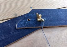
The middle nail establishes the height of the crown - which is a full 5 inches over a 44-inch beam.

sm 3 Model 26 - Crown Radius closeup - hinge and nail.jpg

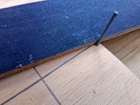
Nails are also driven at each gunwale - just a pencil width below the reference line.


sm 4 Model 26 - Crown Radius - gunwale nail.jpg

The middle nail is then removed.

sm 5 Model 26 - Crown Radius - midline nail removed.jpg

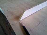
Starting at either end, the gauge is slid over the 2 gunwale nails with a pencil nested at the hinge point.

sm 6 - Model 26 - Crown Radius struck with pencil FLIPPED.jpg

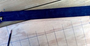
Next I measure the bottom contour by "dropping perpendiculars" from my reference board. It is critical that each measurement be square to the reference board.

sm 7 Model 26 - Perpendiculars Jig 1.jpg

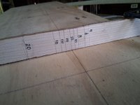
"Depths" for each station (2-inch intervals) are measured with a pointed "tick stick. They are recorded directly onto the stick.

sm 8 Model 26 - Tick Stick - with measurements.jpg

Each depth is transferred to the frame itself.

sm 8b Model 26 - Transferring from Tick Stick at 12 inches from CL.jpg

The next step is "connecting the dots" - with a bit of artistic license. Then , very careful sawing to the lines. I have kept a "strut" in the middle - to be removed later in the process - but to maintain the elevations.

sm 9 Model 26 - Middle Frame on scale 1.jpg

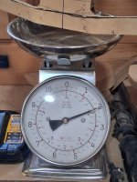
At this point, the mid-frame weighs just a bit over 2 pounds.

sm 12 Model 26 - Middle frame on scale 2.jpg

More to come - but my Mom just got up and needs breakfast!

SJS

Back again.....

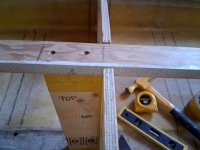
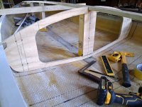
Here is the mid-frame tacked in place - a nice snug fit! The large cutouts at the gunwales were needed for clearance when swinging the frame into place.

The interior edges of the opening will be rounded over on the router table before installation.

sm 14 a Model 26 - Middle Frame tacked in place FULL.jpg

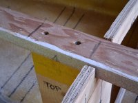
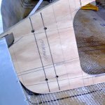
I am not sure of the style I will use for the oarlock stanchions - but I have laid out the location for 1/2-inch pipe stanchions - and for s/s U-bolts to secure them.


sm 14 b - Model 26 - Middle Frame tacked in place - notch and stanchion holes.jpg

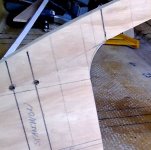
I have started the saw cut where the central portion of the frrame (the upper "rib") will be cut away after framing and decking is complete.

sm 14 c  Model 26 - Middle Frame tacked in place FULL.jpg

Likewise, the "strut" portion of the plywood frame will be sawn away just before the frame is 'glassed into place. Note, too, that this frame will remain open over the keel - to allow bilge water to move freely fore and aft.


sm 14 d Model 26 - Middle Frame tacked in place.jpg

Off to the lumberyard - for another "Mom" project....

All the best,

SJS
 
Last edited:
Steve,

Excellent work as usual. I make a crown gage and then transfer the crown to needed frames.

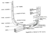
I was rereading Chappelle's description of building a sneakbox in ASSC and you do need a deciphering wheel to translate to more common terminology. Ribs become futtocks and harpins become stem liners in ASSC.

Rick Lathrop
 
Steve

Great tutorial. I'll point out that the arc you created with your crown jig is that of a circle and not an ellipse, in case anyone was wondering. The beauty of this method is you can accurately draw really large arcs without needing a giant compass or a work area at least as big or bigger than the radius.

I really appreciate that you are unlocking the mysteries of how to create parts that fit into an existing hull. Once someone grasps these concepts there is no end to what they can create. You don't need, CAD, CNC, or advanced drafting skills. It's amazing what one can do with sticks (some pointy), a few nails, a pencil, and a brain!
 
Steve

Great tutorial. I'll point out that the arc you created with your crown jig is that of a circle and not an ellipse, in case anyone was wondering. The beauty of this method is you can accurately draw really large arcs without needing a giant compass or a work area at least as big or bigger than the radius.

I really appreciate that you are unlocking the mysteries of how to create parts that fit into an existing hull. Once someone grasps these concepts there is no end to what they can create. You don't need, CAD, CNC, or advanced drafting skills. It's amazing what one can do with sticks (some pointy), a few nails, a pencil, and a brain!
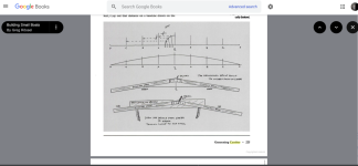
Building Small Boats by Greg Rossel is another good boatbuilding book. Page 224 and 225. You can preview the book on Google Books

1786990470975.png
 
Steve

Great tutorial. I'll point out that the arc you created with your crown jig is that of a circle and not an ellipse, in case anyone was wondering. The beauty of this method is you can accurately draw really large arcs without needing a giant compass or a work area at least as big or bigger than the radius.

I really appreciate that you are unlocking the mysteries of how to create parts that fit into an existing hull. Once someone grasps these concepts there is no end to what they can create. You don't need, CAD, CNC, or advanced drafting skills. It's amazing what one can do with sticks (some pointy), a few nails, a pencil, and a brain!
Eric~

Indeed - the crown is an arc - a section of a circle - and not part of an ellipse. As it is, I am a bit anxious about bending the 1/4-inch plywood onto the deck framing. As all will see once this Top Secret vessel is fully revealed, the profile of the deck has significant camber from stem to stern. Fastening down the plywood will certainly require a bit of "torturing".

Elliptical sections would be even tougher to sheath with plywood. Carvel or strip-building would be needed there.

My biggest ellipse project thus far has been this sign board (Susan was the board president for several years). Just 2 nails and the exact length of (non-stretch) string for the layout.

Co-op Ellipse.jpg

I used MDO for the board - and PVC "lumber"for the trim - dado-ed to fit over the edge of the plywood. A local art teacher led some students in painting the sign - and I urged her to use lettering.com for the text - to save lots of tedious work and with a superior result (I use them for boat names and reg numbers).

BTW: Earlier, I have used the very long beam compass approach for lofting deck crowns.

All the best,

SJS
 
Steve,

Excellent work as usual. I make a crown gage and then transfer the crown to needed frames.

I was rereading Chappelle's description of building a sneakbox in ASSC and you do need a deciphering wheel to translate to more common terminology. Ribs become futtocks and harpins become stem liners in ASSC.

Rick Lathrop
Rick~

Hmmm??? IN this old brain, futtocks are sawn sections of (heavy) frames....


Futtocks 2.jpg

"Rib" is just lubberly slang for frame.....(mostly for lighter bent (steamed) frames).


Looks like I need to check up on Mr. Chapelle....sounds like he has strayed off the reservation....
Book - Chappelle cover.jpg
Stay tuned!
SJS
 
Rick~

Hmmm??? IN this old brain, futtocks are sawn sections of (heavy) frames....


View attachment 78671

"Rib" is just lubberly slang for frame.....(mostly for lighter bent (steamed) frames).


Looks like I need to check up on Mr. Chapelle....sounds like he has strayed off the reservation....
View attachment 78670
Stay tuned!
SJS
Steve,

You need to set Howard straight.
 

Attachments

  • IMG_0975.jpeg
    IMG_0975.jpeg
    507.4 KB · Views: 4
Rick~

I think I see where Mr. Chapelle was coming from... each station includes both the bottom frames and the deck beams - sort of how I am doing it with plywood. As he describes a multi-part assembly, it makes sense that each part would be a futtock.

In my Benjamin Hallock Scooter, the forward frames were sawn from 2 pieces - top and bottom - and serve as one "station".


Hallock Scooter frames.jpg

Similarly - within the cockpit - each frame includes 2 pieces (actually sawn hackmatack knees) which are paired and bypass each other. So, two futtocks per frame.

sm 14 -  Finished interior.jpg

So, I will give Mr. Chapelle a pass on this one.....

All the best,

SJS
 
Consulting Google AI this is how it defines the terms before going into a deeper dive.

  • Frame: The complete, transverse "U" or "V" shaped rib structure extending from one side of the boat to the other.
  • Rib: A lightweight, flexible piece of wood bent into shape using steam.
  • Futtock: A short, pre-curved piece of solid wood joined together with other pieces to build a large frame.
 
Back
Top