What's on your Workbench - APRIL 2023

All~


Got a few birds to the DONE stage - a few Grey Ducks - but Drakes only thus far.


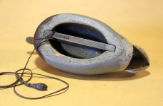
This Herter's Model 63 came to me as a Mallard (?):
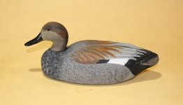

Herters Model 63 - Gadwall Drake - on bench.JPG


This is an E Allen Gadwall - the first Gadwall I've done from this maker.


E Allen Gadwall Drake - Eric Henry - on bench.JPG


There will be 4 Grey Ducks altogether - and each will get a flush, unballasted keel because they will be used for carry-in hunts on small waters. I have a rig like this - Mallards, Blacks, Woodlies - for small waters hereabouts. Note the 2-ounce bank sinker I use for the "anchor".


E Allen Mallard - flush keel on SJS Mallard.JPG


Here are the 2 Drakes in natural light. Their Hens are half-done. It's tough to see in this photo, but I sliced a small wedge off the neck on the starboard bird - to give a slightly different attitude. The port bird - which was the one on the bench - is the stock head.



E Allen Gadwall Drakes - E Henry - on lawn.JPG


All the best,


SJS


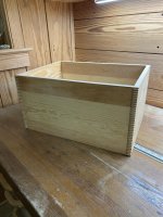
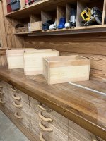
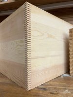
At long last I finished the Morgan Lock Corner machine project. As previously mentioned I bought it to make gunning boxes. The below pictures are of the first boxes I've made with it. Not gunning boxes, but rather shop crates to help me learn how to use the machine and get to know it better. The pictures below are from today after dry fitting the sides. I'll glue them up tomorrow, but suffice to say I'm thrilled with how well this machine cuts box joints. These crates are 12" t0 14" tall so that means the room for error is small or the joints wouldn't fit. They went together nicely.

The link below is to an Instagram video that will be up until tomorrow.

https://www.instagram.com/stories/duckboatsdotnet/3077478404835397836/


Img_5422.jpg


Img_5430.jpg


Img_5428.jpg
 
Last edited:
Eric,

Looks great. Will you be cutting the hand pulls?

Now you need one of these to complete the collection.

https://www.alamy.com/patent-model-of-a-rotary-printing-press-for-printing-or-branding-wooden-box-covers-this-patent-model-demonstrates-an-invention-for-a-rotary-printing-press-which-was-granted-patent-number-194902-this-press-had-a-feed-table-to-steer-boards-between-the-impression-cylinder-and-the-hollow-plate-cylinder-the-inking-apparatus-was-overhead-image359443377.html
 
Carl

You can by rearranging the cutterhead stack. The fingers are 5/32" now with cutter, spacer, cutter, spacer. I could rearrange things to, say, cutter, cutter, spacer, spacer for 5/16" fingers. The downside is you have to take the whole thing apart to make such a change. I'll be sticking with it the way it is for a while.

Richard

I am going to add hand pulls. Probably simple oval cut-outs. These boxes are going on a shelf and there isn't much room left for something to protrude. That printer is cool. When I was researching this machine I was amazed at the industry and machinery that at one time existed to support crate and box making. Then came cardboard...

Eric
 
Eric Patterson said:
At long last I finished the Morgan Lock Corner machine project. As previously mentioned I bought it to make gunning boxes. The below pictures are of the first boxes I've made with it. Not gunning boxes, but rather shop crates to help me learn how to use the machine and get to know it better. The pictures below are from today after dry fitting the sides. I'll glue them up tomorrow, but suffice to say I'm thrilled with how well this machine cuts box joints. These crates are 12" t0 14" tall so that means the room for error is small or the joints wouldn't fit. They went together nicely.

Eric,
Holey buckets, that's a lot of fingers.

I've only done one box where I cut box joints for the corners. I cut those on a homemade jig using a table saw. Can't imagine the repetitiveness of cutting fingers, one by one, box after box, day after day, without the use of one of those machines to simplify the process. That had to be extremely satisfying when all four sides slipped together as they should.

EDIT; I remember repurposing many a crate box for storage of most anything. The thing I remember is, many of the side panels were one solid piece of wood, not a glue up. Sure many of the panels dried out and cracked but the finger joints on the corners held everything together.
 
Last edited:
Joe

Thanks. I hope to work on more boxes as time allows. Right now we are about to start food plot efforts so that will keep me out of the shop until the seed is in the ground.

Dave

I saw a video the other day of someone cutting box joints on CNC. They are done one-at-a-time but at least you can be doing other work while the laborious task is handled by the CNC. In all honesty this machine may be overkill for the boxes I'll make, but I get satisfaction using century old machinery that is mostly forgotten. Nothing wrong with doing the fingers by tablesaw or router. The flexibility in finger size and spacing certainly offers an advantage and the cut is probably a little cleaner given the number of teeth a sawblade has when compared to the two tips on each Morgan cutter.

Eric.
 
Eric,

I plan to add a vertical table to my CNC router build to allow box and dovetails. SDR I hope to do some duck related carving when it is completed.

Rick
 
Richard

I think at some point I'll get a CNC router. What I'm unclear on is how you go from an idea in your head to making the machine move. I've never done any computer drafting and don't know the steps to go from paper sketches to machine instructions. It's simply not anything I've ever been exposed to. If you have any recommendations, I'd like to hear them. I tried watching some youtube videos but they were lacking in detail or went into way too much detail and moved too slowly for my attention span. Surely there is a good primer out there for someone starting with no knowledge.

Eric
 
The most popular design software is Vectric, https://www.vectric.com. I use VCarve Pro, there is other software like Fusion 360 but VCarve is a usual choice. You design in VCarve and then output the computer control code (GCode).
Another piece of software (Mach 3-4) is used to run the GCode. Mach interprets the GCode into the step and direction for your stepper motors.

There is a box gadget to cut boxes on your CNC.

https://gadgets.vectric.com/v9/box_creator

Rick
 
Last edited:


Eric Patterson said:
Richard

I think at some point I'll get a CNC router. What I'm unclear on is how you go from an idea in your head to making the machine move. I've never done any computer drafting and don't know the steps to go from paper sketches to machine instructions. It's simply not anything I've ever been exposed to. If you have any recommendations, I'd like to hear them. I tried watching some youtube videos but they were lacking in detail or went into way too much detail and moved too slowly for my attention span. Surely there is a good primer out there for someone starting with no knowledge.

Eric

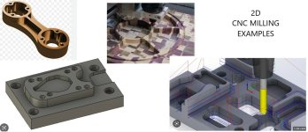
I could tell you but then I would have to kill you for making me think about work. [cool] Drawing up a piece in 2D and programming that is fairly simple. Don't get me wrong there is still depth in 2D. The X and Y axis move to cut geometric shapes while the Z axis cuts at a predetermined depth.


Untitled.jpgimage001.jpg
As you can see, one can do quite a bit with 2D drawings and programming.


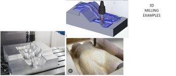
When you step up to 3D programming that gets a bit more complicated, both in the drawing aspect as well as the programming aspect.


3D.jpg

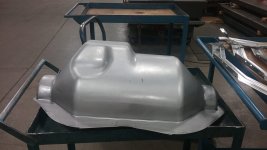
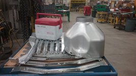
I cut the tool steel block which punched out this form in a piece of sheet metal. This required 3D programming. My machine was capable but I needed assistance to write the program. The part is a heat shield for a muffler.


form002.jpg


form001.jpg


I was just getting into true 3D programming when I retired. I have since played with Fusion 360 (free version) to create a few 3D drawings.
 
Dave,

I have used Fusion360 to design 3D objects for printing with my 3d printer. I am still learning.

I use Vectric software that does 2.5D but there is a plugin to their Design and Make store where you can buy and import 3d objects for carving. To keep it duck related they have a duck collection you can use to design panels.

Duck%20Panel%20-%20Example%20No.7.jpg__053ae426-e131-47e7-b082-a039fa700f90

https://store.designandmake.com/shop/product/20

There true 3d design product is called Aspire and it cost more then I wanted to spend.

Rick Lathrop
 

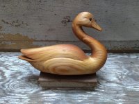
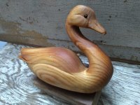
3D, hand carved Sugar Pine, 9" x 6" x 1 3/4". Sealed ready for sanding then paint. Will have to wait, time for Trout. Tis the season.


20230324_133713.jpg20230324_133917.jpg
 
Richard and Dave

You lightly touched on something that I do not understand. That being the fundamental flow of data. Okay, you use VCarve Pro for the design stage to draw your part. Then what? Does VCarve on your PC then produce GCode and pipe it straight to your CNC router? USB or some other interface? Or are there intervening steps, hardware, and other software needed? What are the building blocks of the set-up to go from ideas in your head to a CNC router moving around the table and removing wood? I'm talking very simple block diagram type stuff here...

Eric
 
Eric,

VCarve Pro does both CAD and CAM. You design the part setting the material size and thickness and the location of the shape in the material. These are done a vectors. Once you are done with your design you then select the design and do the CAM where you assign a bit, for example a 1/4 inch 2 flute router bit, cutting depth and other variables. When you are complete you have VCarve export the GCode. It can go direct to a machine or a file system. I run the CNC router control software on a separate Window XP since it has a printer parallel port to connect to the breakout card. I load the file from VCarve on the XP machine using a thumb drive I then set up the material in the machine. I install the bit in the router, set the router to the zero coordinates and then have Mach3 run the program.

Site for Mach4, newest version. https://www.machsupport.com/software/mach4/

Rick
 
Last edited:
Rick

Thanks. That help bring things into focus. In a nutshell what I gather is you use a PC (or perhaps a Mac) with design software to draw the item you want to make, and that info is stored in a file of some known format (dxf?) that a later step in the process understands. Then you take the file to another PC, via a thumb drive transfer. That PC is physically connected to the CNC router and runs software, Mach3, that allows you to set up initial conditions, so the router and PC are aware of the stock's location on the table, the router's location relative to the stock, and tooling parameters such as diameter, length, shape, etc.. With all that info in hand the Mach 3 software takes the file converts it to a standard language, gcode, which the drives the router along a path to remove stock thus yielding the part you seek to create.

Have I got the gist of it? Any glaring problems?

Thanks for your time.

Eric
 
Last edited:
Eric,

Yes, basic idea. You can run only one PC/laptop if you want and I am sure many do. VCarve will output the GCode.

For the sneakbox sign I created the output code in text file looks like this. Basically go to this X Y Z location there are gcode specifc functions like G94 and G1 but those are placed by VCarve.

( SneakBox_12x12_50_90degreeVBit )
( File created: Wednesday April 15 2020 - 03:36 PM)
( for Mach2/3 from Vectric )
( Material Size)
( X= 11.750, Y= 12.000, Z= 0.750)
()
(Toolpaths used in this file:)
(V-Carve 1)
(V-Carve 2)
(V-Carve 3)
(V-Carve 4)
(Tools used in this file: )
(1 = V-Bit {90 deg 0.5"})
N130G00G20G17G90G40G49G80
N140G70G91.1
N150T1M06
N160 (V-Bit {90 deg 0.5"})
N170G00G43Z0.7874H1
N180S16000M03
N190(Toolpath:- V-Carve 1)
N200()
N210G94
N220X0.0000Y0.0000F30.0
N230G00X1.8558Y6.1229Z0.2362
N240G1Z-0.0432F15.0
N250G1X1.8611Y6.1288Z-0.0379F30.0

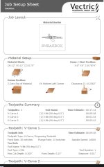
VCarve will also generate a summary worksheet so you know which bits to put into the machine.

We can continue on PM if you want to not hijack the duckboats forum.

Rick


SneakBoxJobSheet.jpg
 
Back
Top