Steve Sanford
Well-known member
Good morning, All~
The next step was 'glassing the decks. Since it is always a messy job - no matter how I learn to "work clean" - I minimize the photodocumentation for the sake of my camera and tripod. Also, I followed conventional processes, to use 6-ounce cloth and epoxy resin. As I have for the past 3 or so years, I get all my supplies from U S Composites. Specifically, I use their 635 Thin Epoxy System with their 3:1 Medium Hardener.
http://www.uscomposites.com/epoxy.html
I use graduated mixing cups instead of pumps. I actually bought a set of pumps a while back but have not even ripped open the package. My applicators include foam brushes, foam rollers and squeegees. Since I am working in my shop, the wood stove ensures thorough overnight curing.
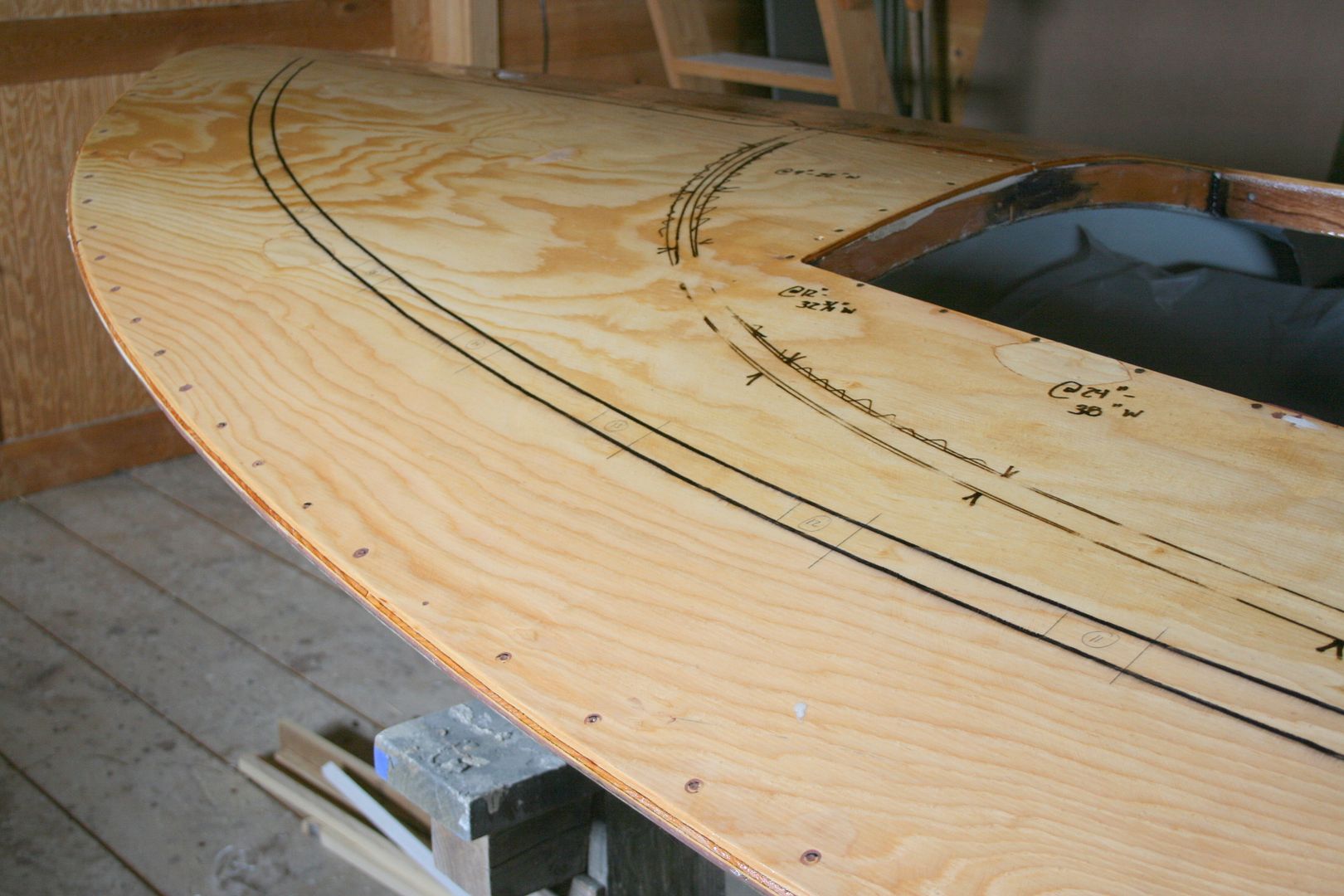
Notice that I marked out the locations of deck "appurtenances" - rails and oarlock stanchions - with a bold marker so I could locate them after the 'glassing.
My basic process is:
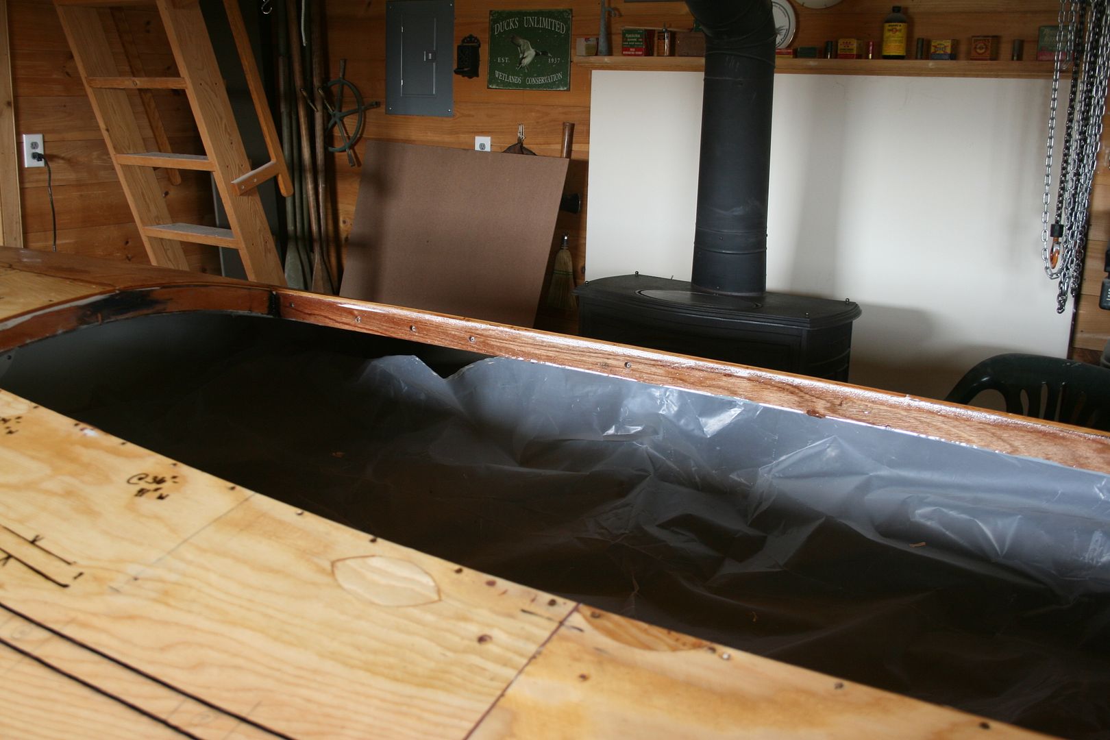
Day 1. Roll on a sealing coat. Let cure with temps above 70 degrees. I line interior with plastic to catch drips and dust.
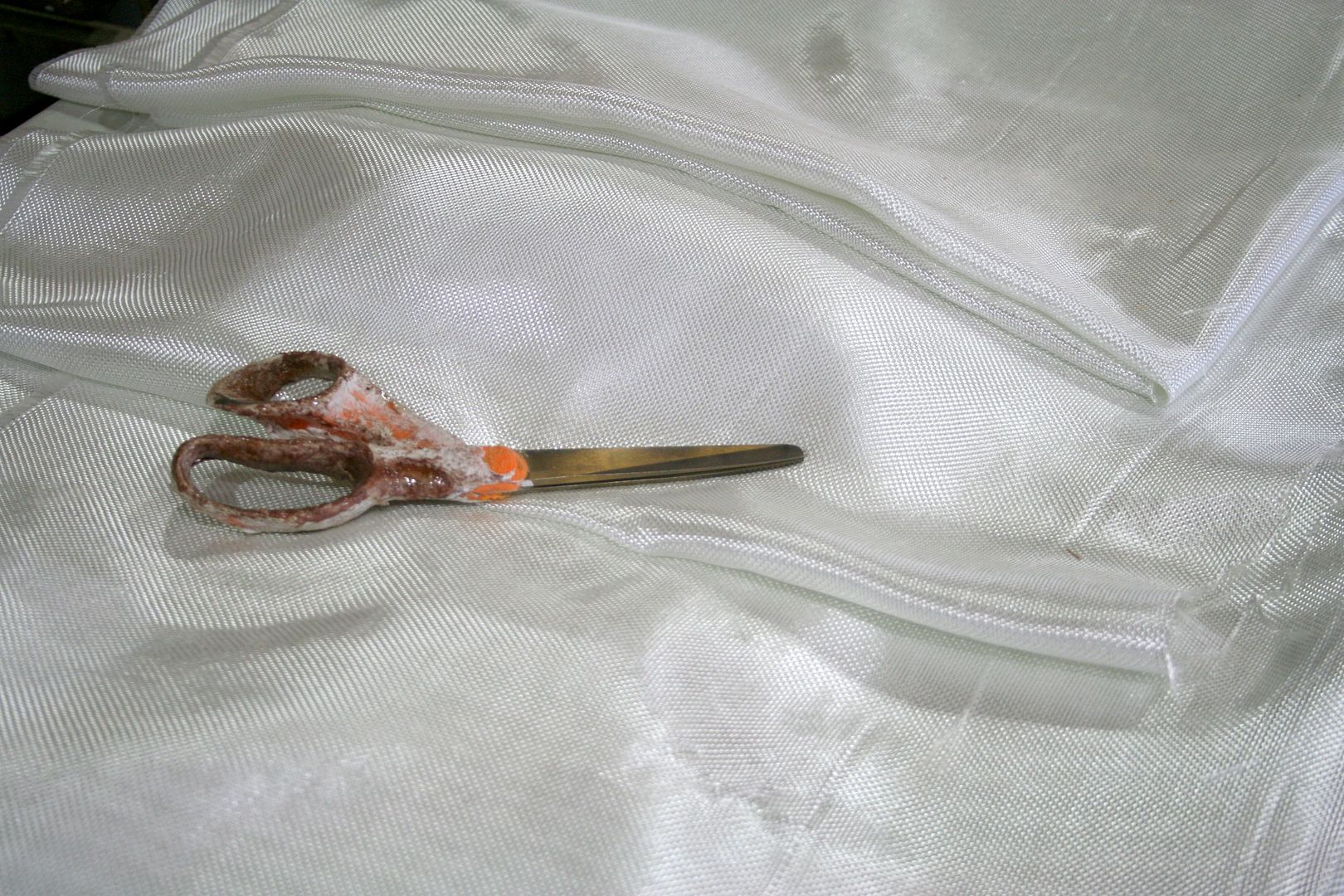
Day 2. Scuff surface with 80-grit orbital sander. After cutting cloth pieces to approximate (over large) sizes, I wet an area, lay on cloth, then apply a saturation coat using a combination of brush, squeegee and roller. Let cure overnight.

Day 3. Grind overlaps and wrinkles with disc sander (60 grit) then sand entire decks with orbital sander (80 or 100 grit). I had some areas that required filler and even small patches, so I added a day. Once they cured, I rolled on a final coat of straight resin.
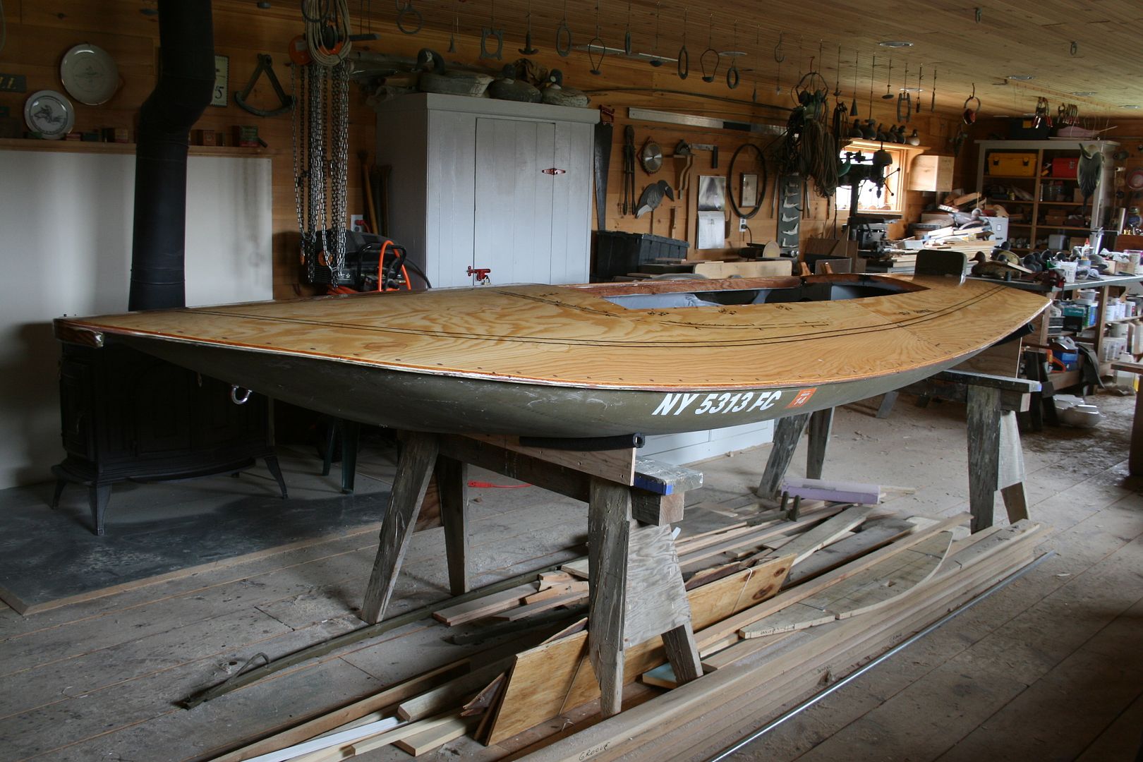
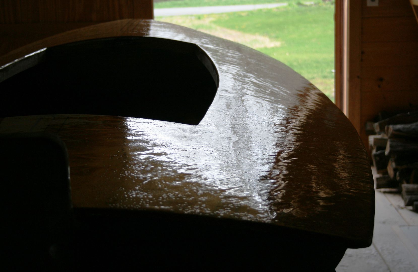
Day 4. Sand entire decks with orbital sander (120 or 150 grit) so they are ready to receive either paint or 3M 5200 Marine Sealant.
The next job was installing the coamings. I had made them previously (from Cypress) - and bored and countersunk the holes for screws - and sealed them with a single coat of epoxy. I also sanded them to get them ready to accept both 5200 and paint.
Installation was straightforward. I did NOT bed the coamings in 5200. Rather, I used the 5200 in the corners - as an adhesive - and laid a bead just below the deck line. My goal was to have a weathertight seal BUT not adhere the coaming to the entire face of the framing. This way, if I ever need to replace a coaming board, I can probably remove it without too much trouble.
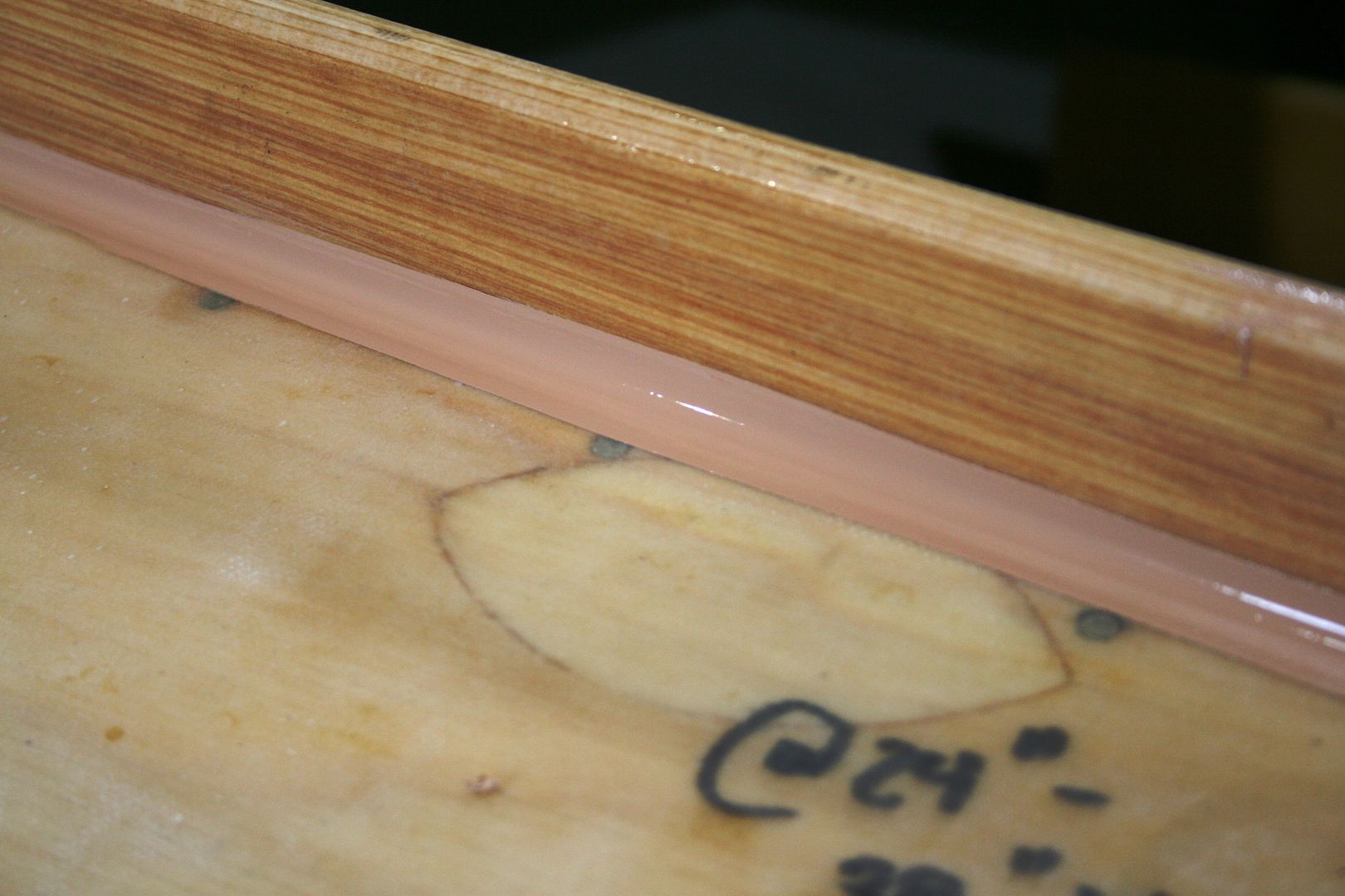

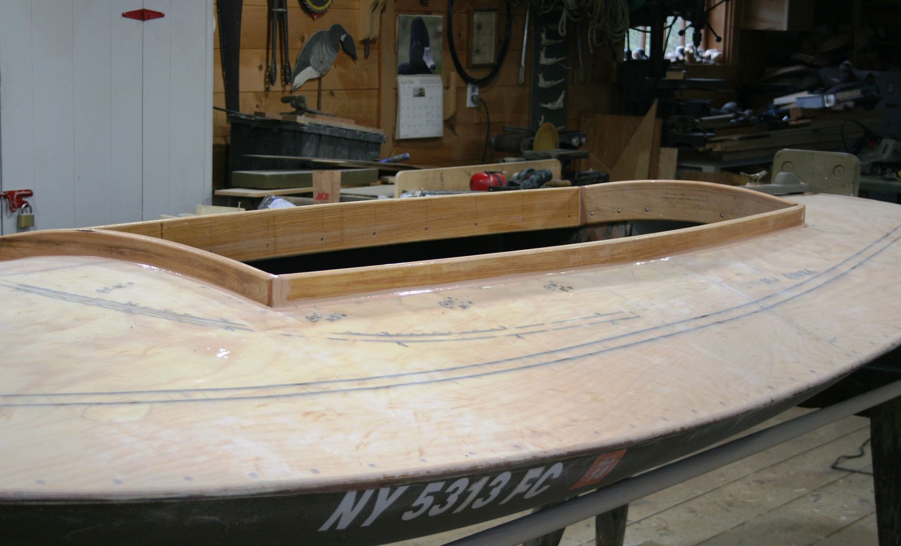
I will round over the outside corners of the coamings - and re-seal them with epoxy - after the 5200 cures fully.
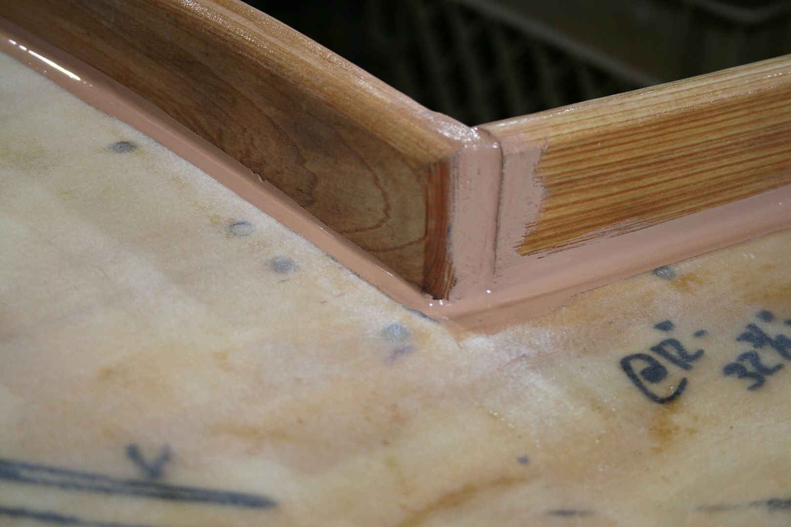
The next job was installing the rails. In this post I will cover the center line rails on the bow and stern and the toe rail for the spray dodger.
I stretched mason's twine taut to make sure the centerline rails were both on center and straight. The black markings were close but not dead on.
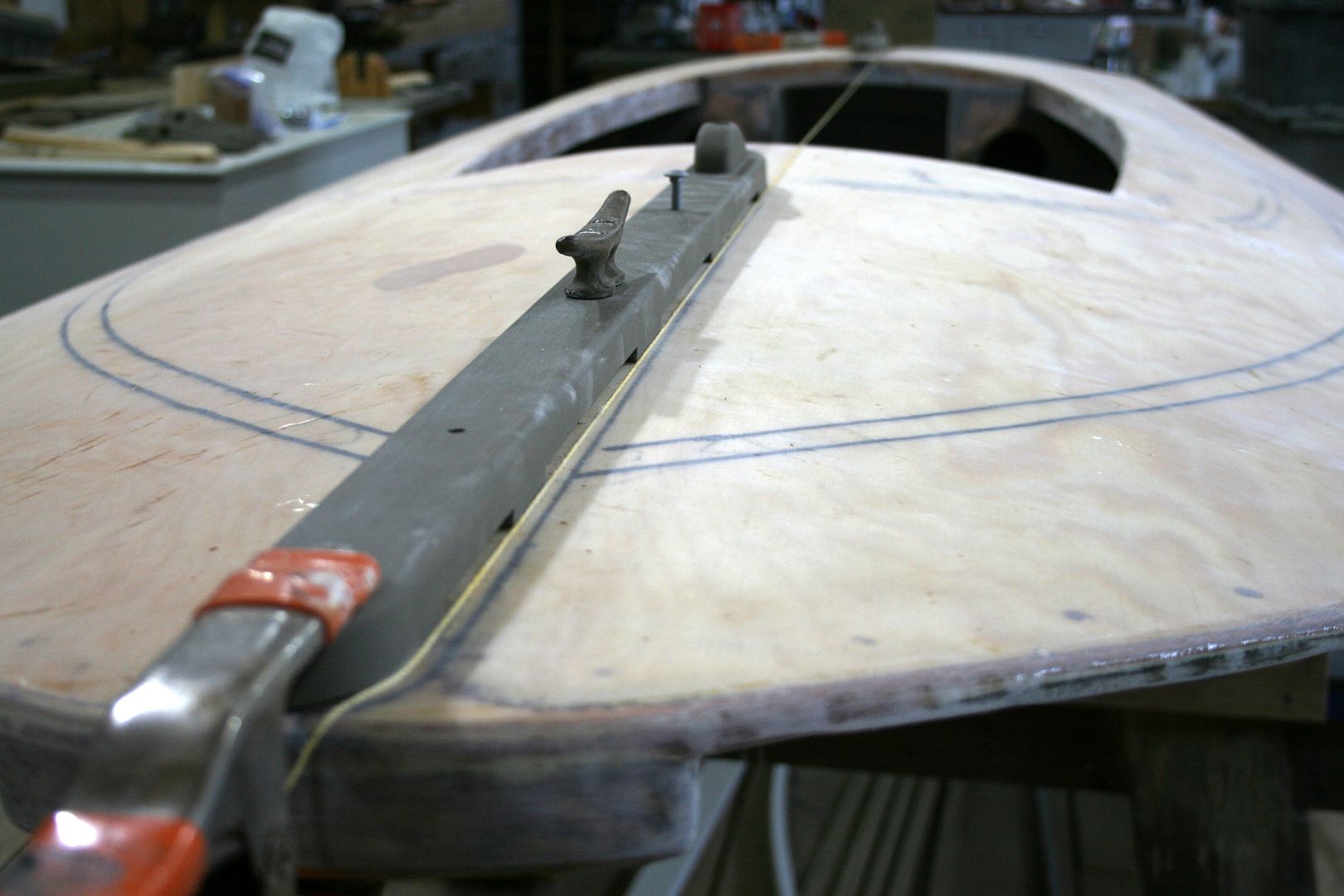
Next, I bored the holes for each of the fasteners. Because these center rails served several functions, fastener sizes and types varied. More than one trip to the hardware store ensued.
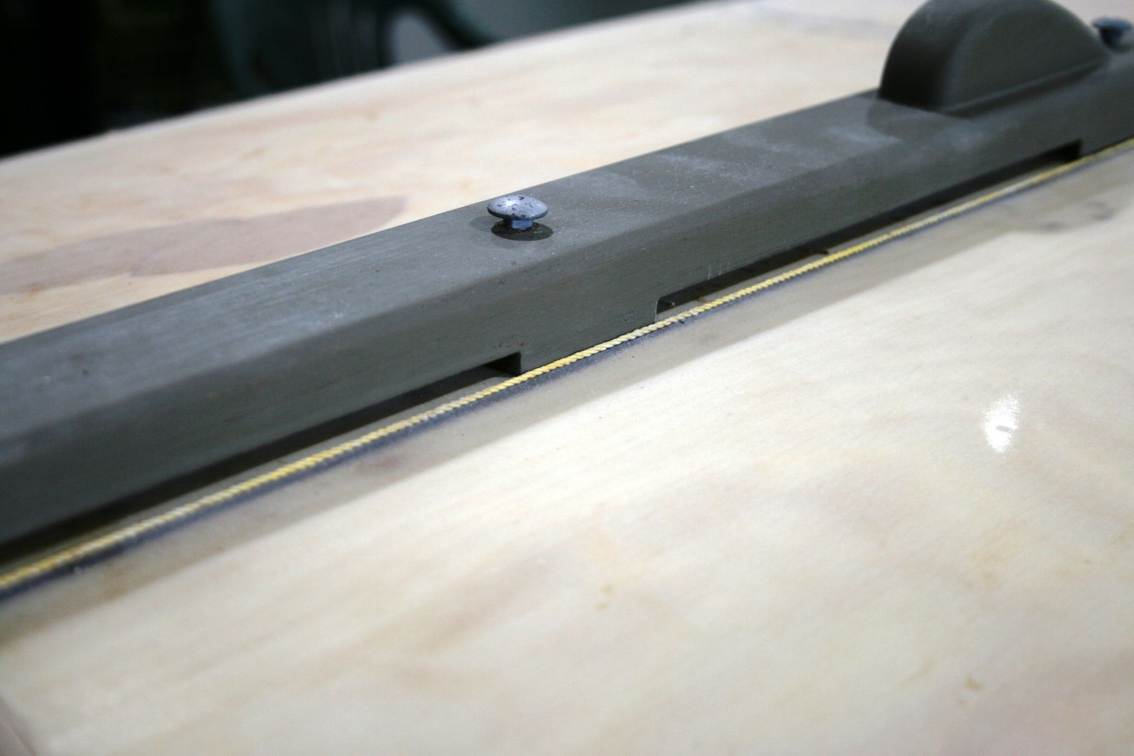
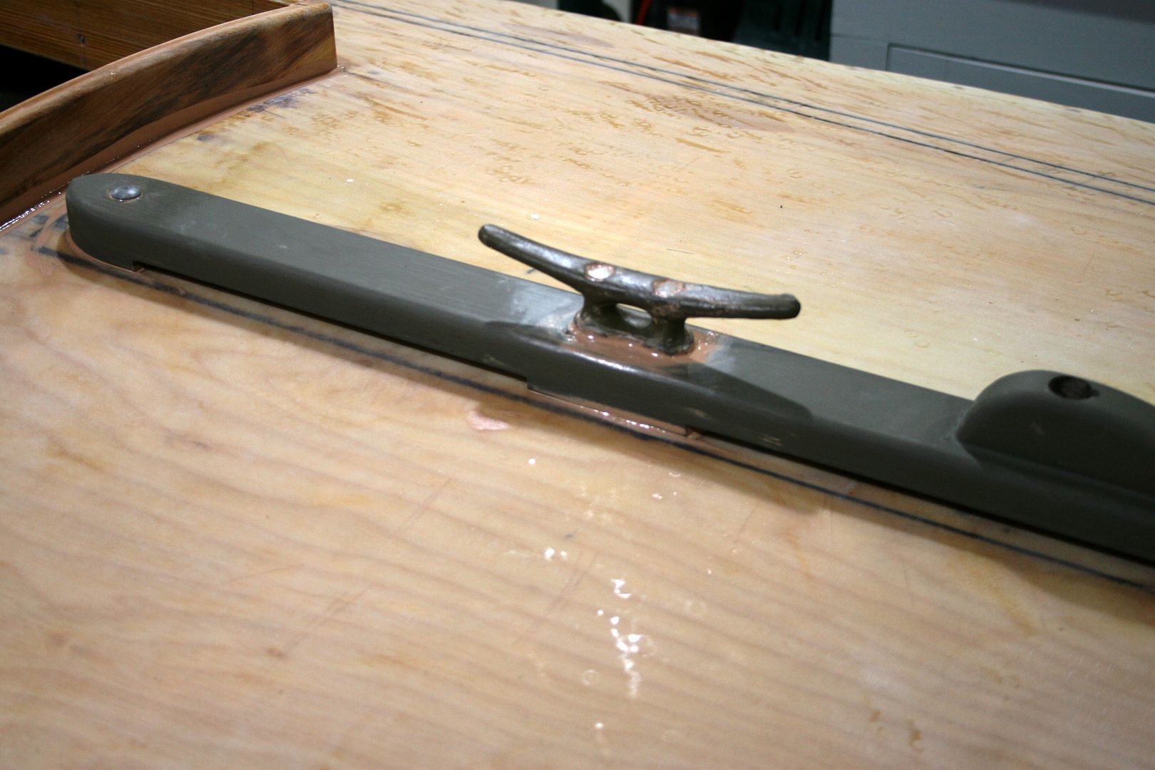
The rails were bedded generously with 3M 5200 allowing for plenty of squeeze out - but no voids.
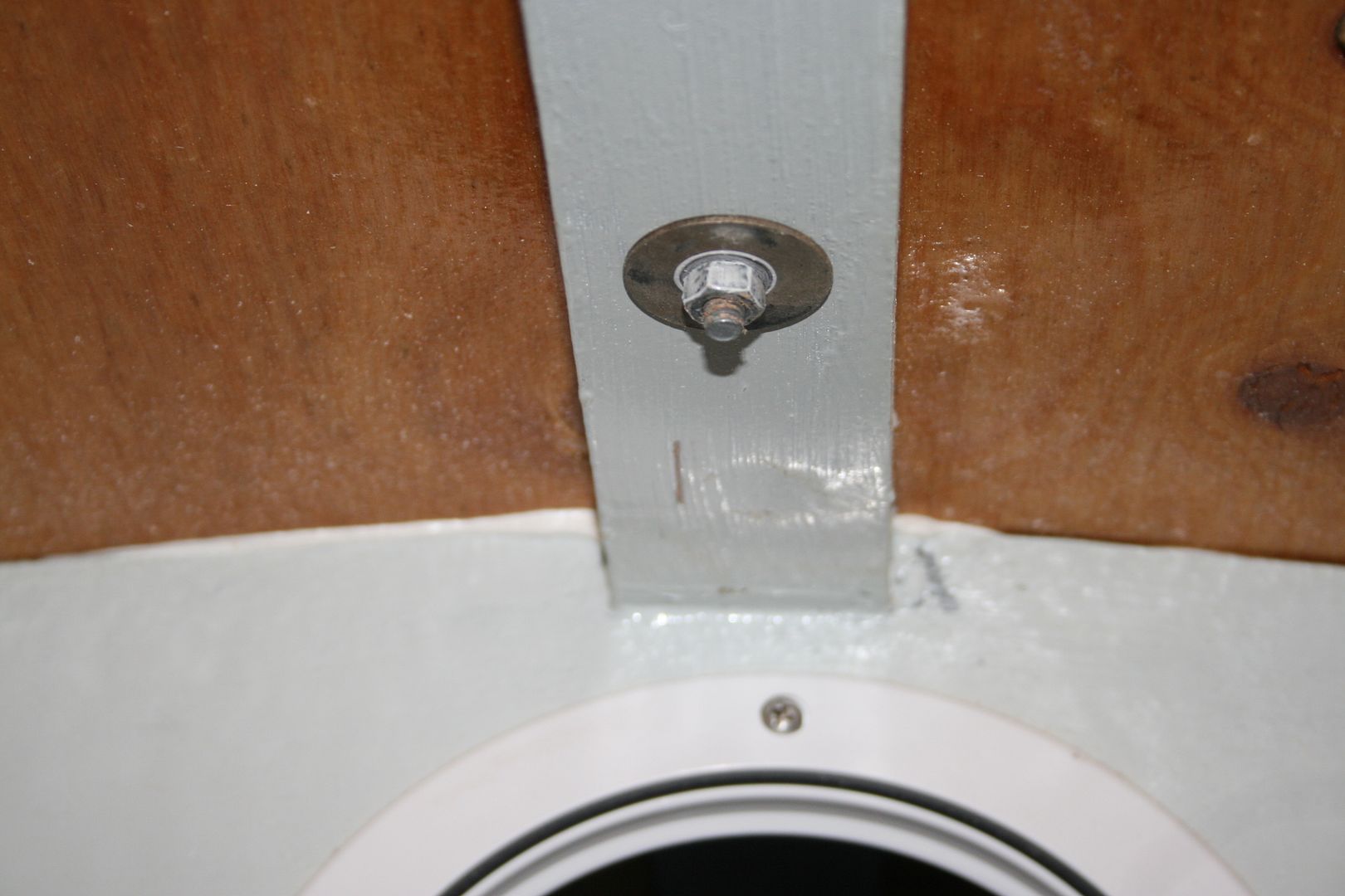
Most of the fasteners were bolts backed up with washers and nuts - fender washers wherever space allowed. Some fastening required a bit of Class IV spelunking.....
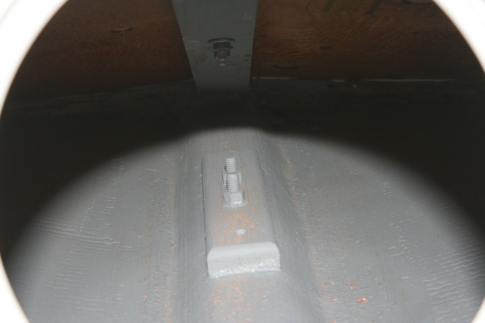
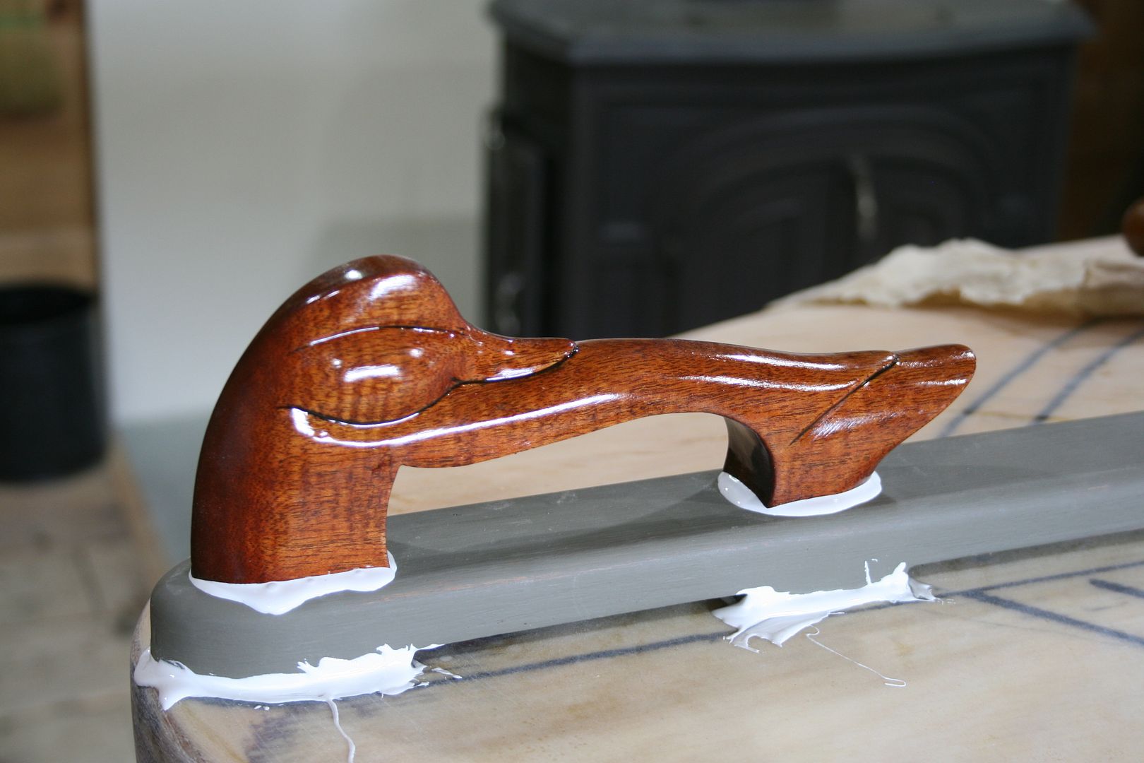
The bow handle (hood ornament ?) was fastened from below with 2 s/s lag screws that run well up into the handle itself - so it can actually be used as a handle - provided the user is wearing a fresh pair of deerskin gloves.....
All excess 5200 gets wiped away before curing.
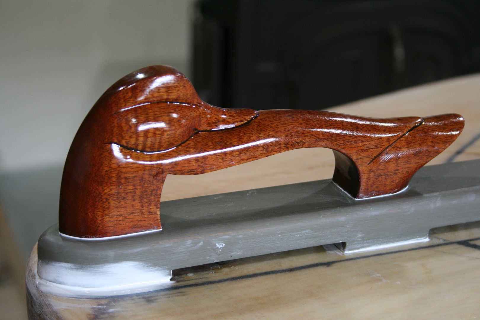
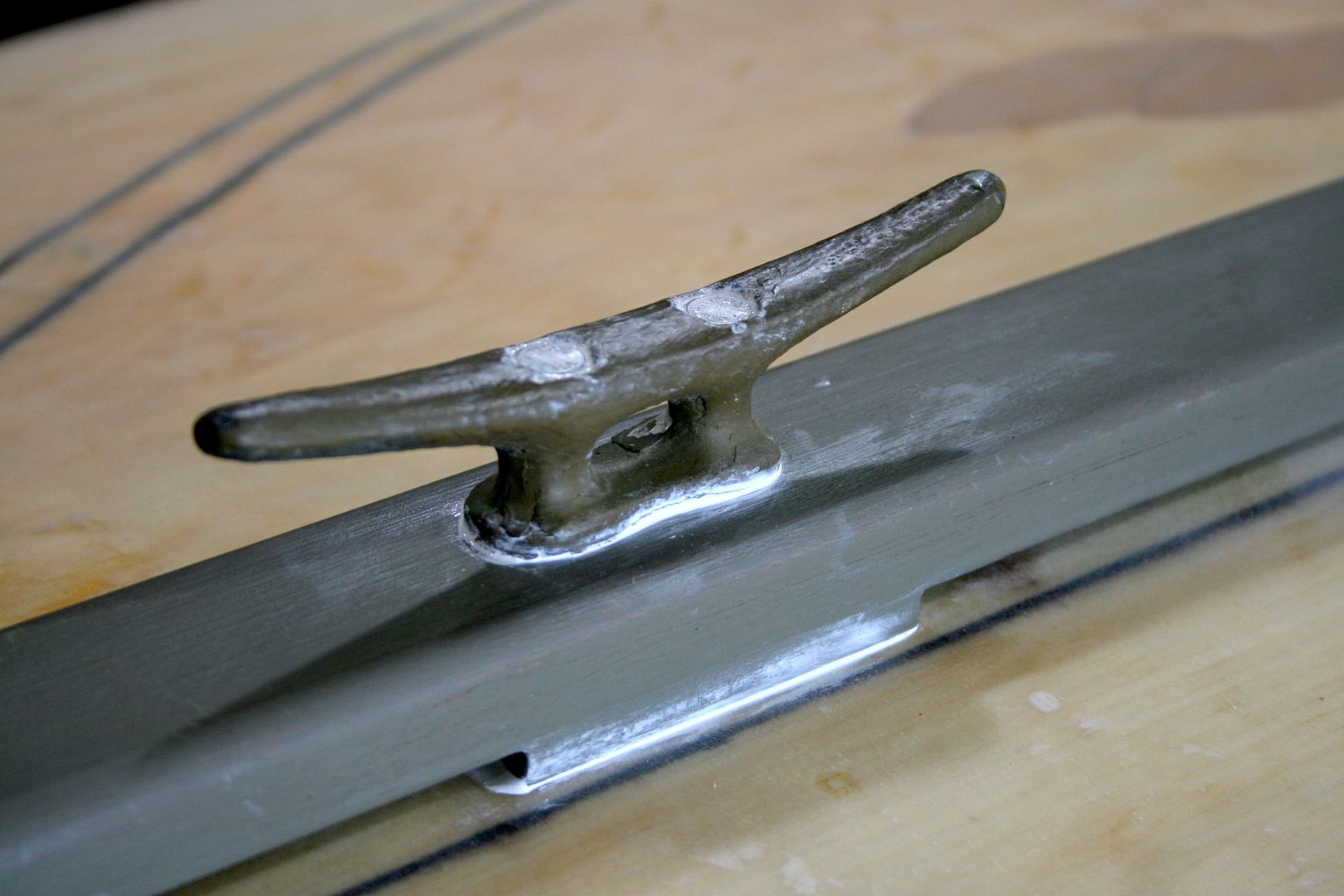
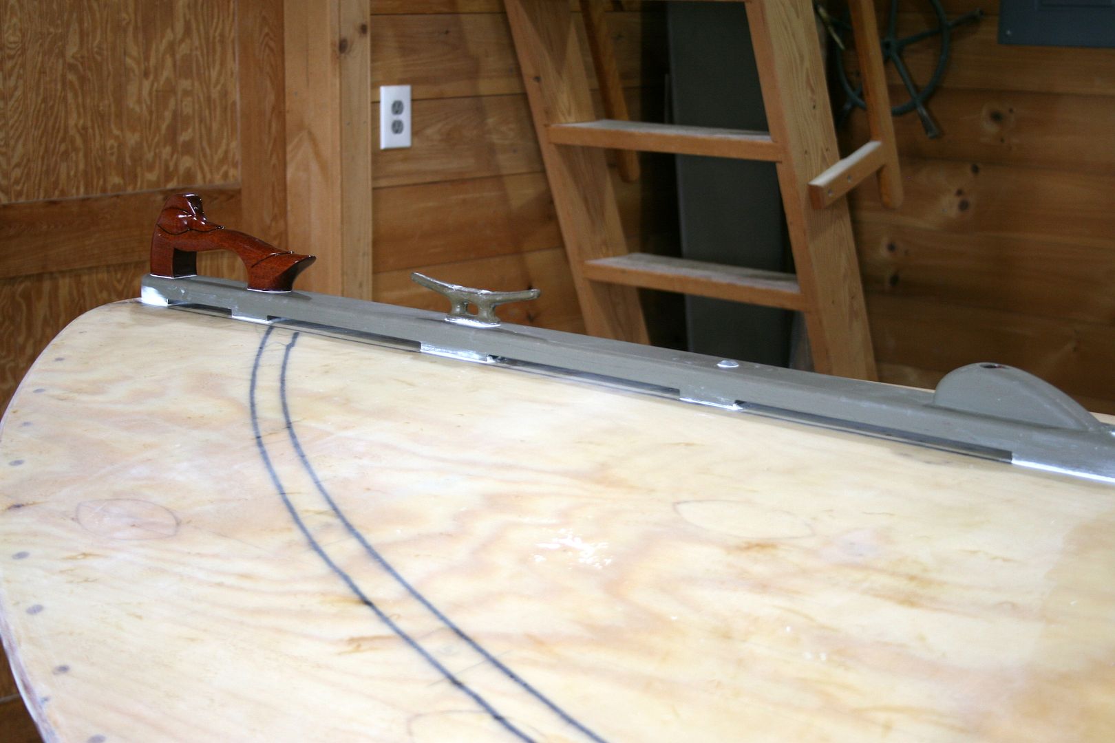
The next job encountered some head seas....

The first attempt ALMOST worked out fine. The problems began long before installation. First, I wondered if the holes required for 1/4-inch fasteners would weaken the 3/4 PVC "lumber" too much. So, when I laid out both the fastener locations and the snap locations, I told myself NOT to bore a hole in the middle of the deck. It is an especially stressful location because the toe rail - bent to its tightest radius - also crosses over a high spot on the mid-line. (The rail is 1-1/4 inches tall - to receive the snaps.) Nevertheless - the road to Davy Jones' Locker being paved with the best of intentions - the very first hole I bored on the drill press was the unforgiving centerline spot. It was in the back of my mind when I began to bolt the rail to the deck, 3M 5200 and all.
At first, I was amazed at how perfectly my process was working. I had bent the rail into its bow shape with some light line. Starting just to the left of center, I drew each carriage bolt down slowly. I could watch the rail above decks while turning the nut driver below decks. The shoulders of each bolt sank snugly into the PVC and the 5200 squeezed out as planned.
I completed the port side and then turned my attentions to the starboard rail. The head of the first bolt was a bit proud and needed some gentle persuasion - in the form of a hammer. After extricating myself from the cockpit - via step ladder - I applied just the right amount of force to the offending bolt. Just enough, it turns out, to immediately explode the rail - right at the unnecessary hole I had bored on the press......
So, off to buy some more PVC - AND to buy some lighter fasteners. Instead of 1/4-inch galvanized carriage bolts, I used 10-24 s/s panhead machine screws. The new holes are 1/8-inch instead of 1/4-inch.
The second installation went as planned. I can now post a sign at my shop door: "No catastrophic failures for 2 days....."
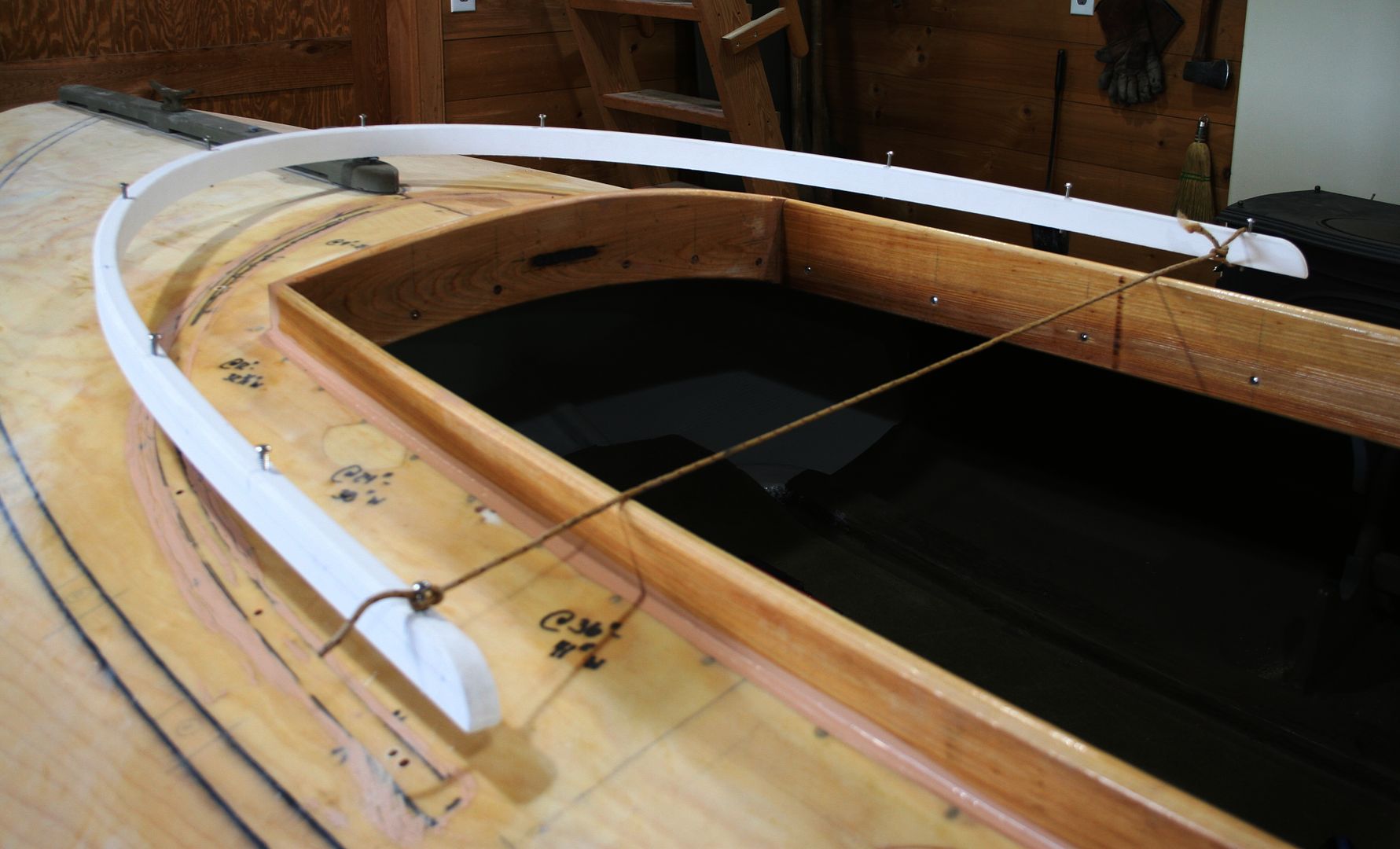
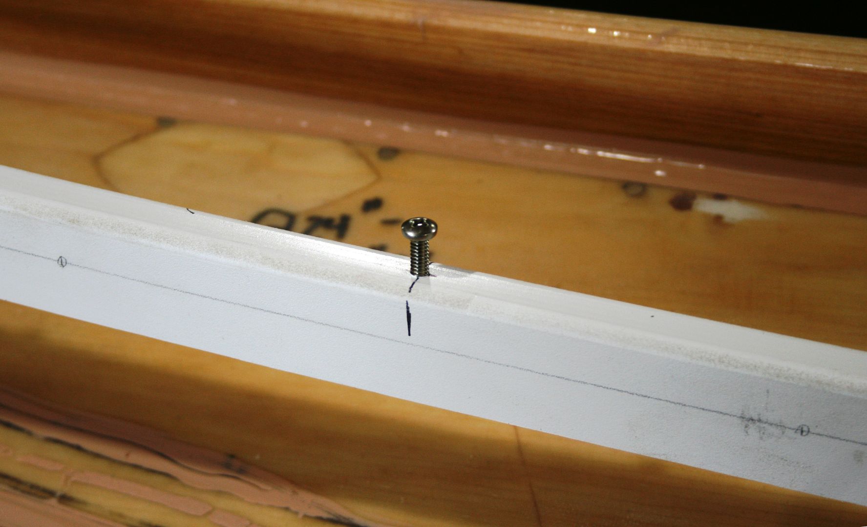

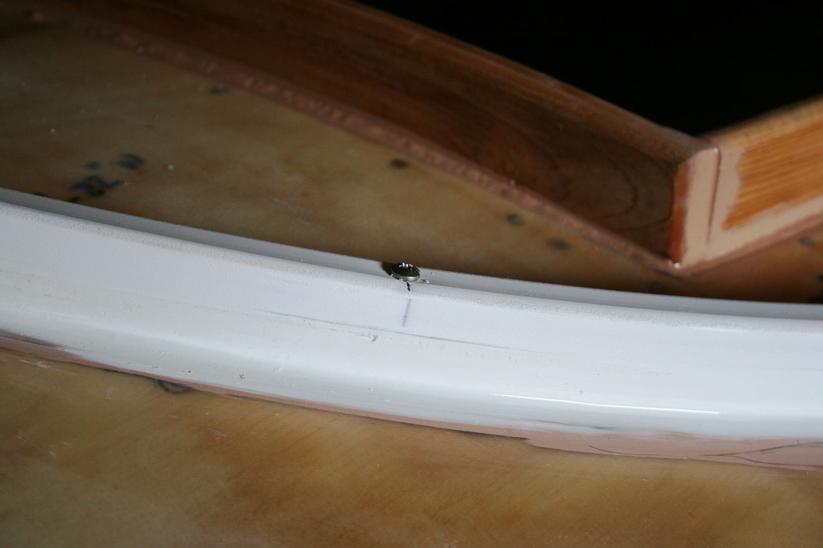
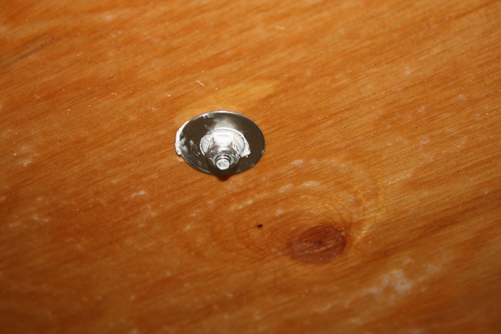
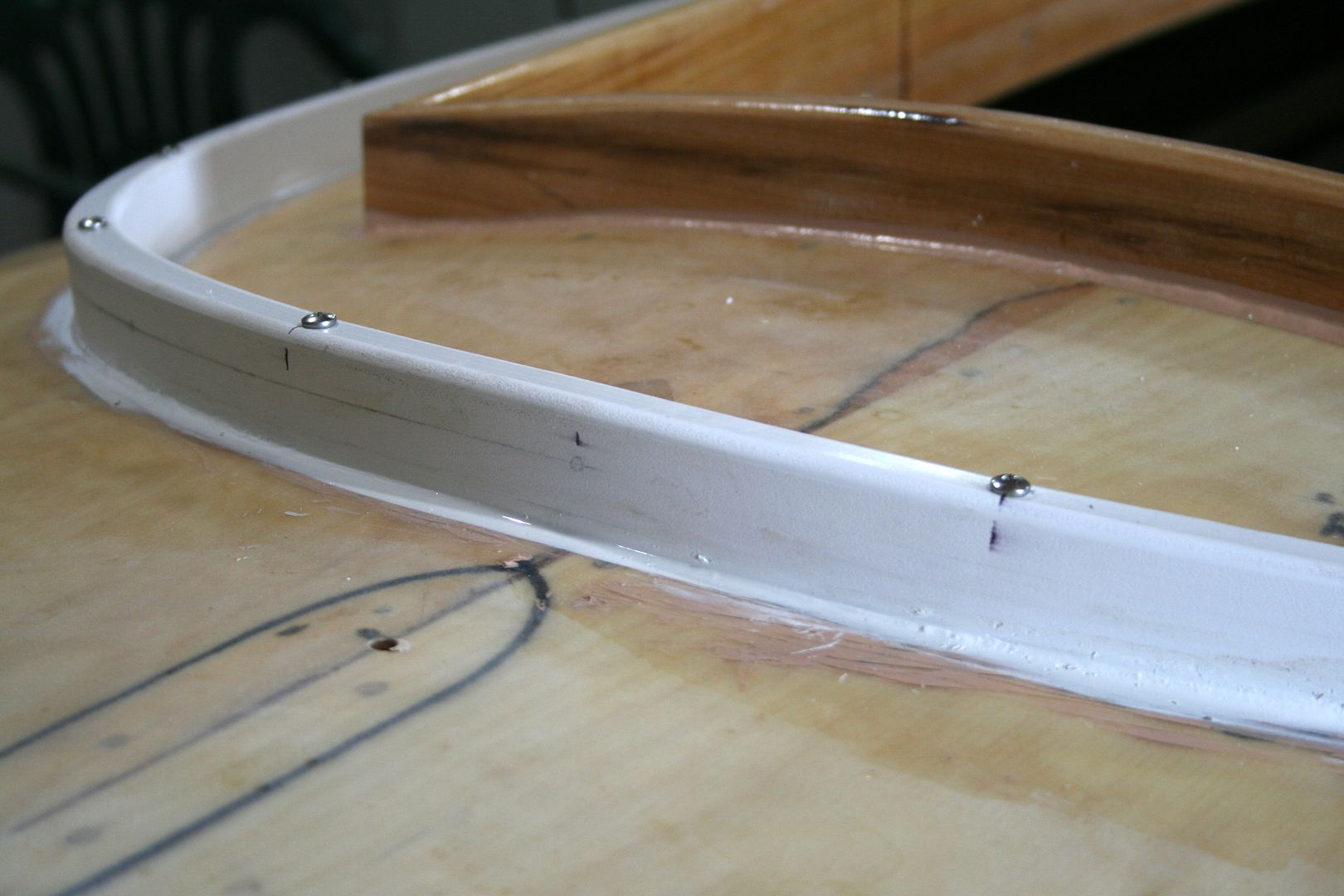
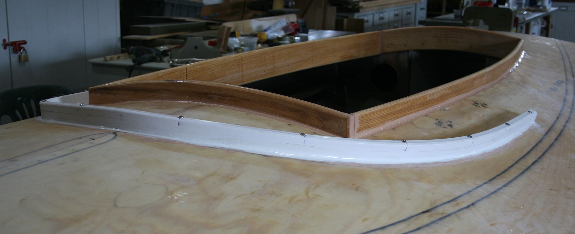
I have limited experience with PVC lumber. I have used it on one other toe rail. Its job is to hold the lower edge of my spray dodger. I am expecting this application will be sufficiently strong once the 5200 cures fully. I did have the thought, though, that 'glassing such a rail to the deck would probably make it truly bulletproof.
Next job is installing the port and starboard thatch rails and oarlock stanchions.
The thatch rails have been fabricated and just need sealing. I had planned to use some vertical grain Douglasfir but I lost confidence when I planed it to size.
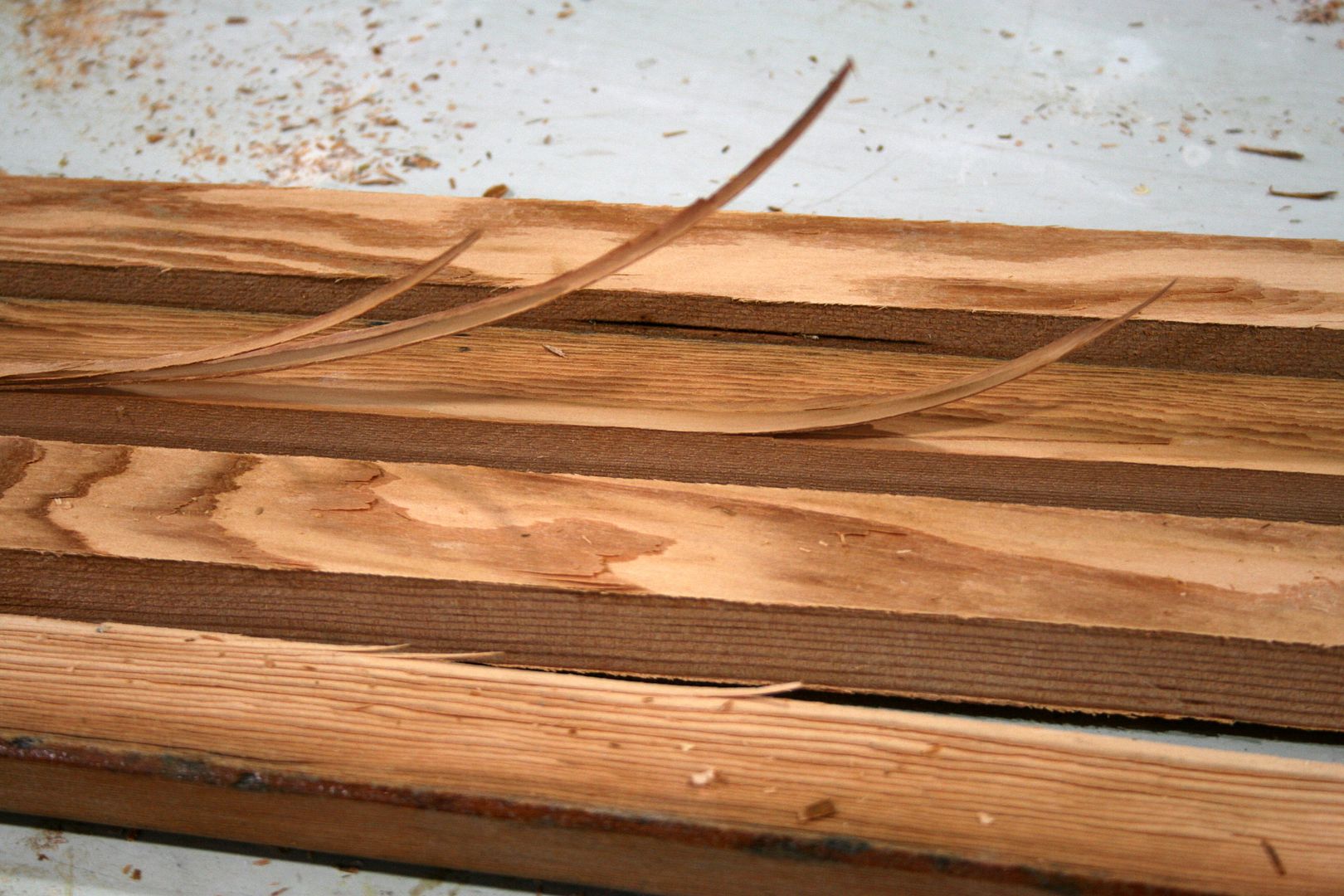
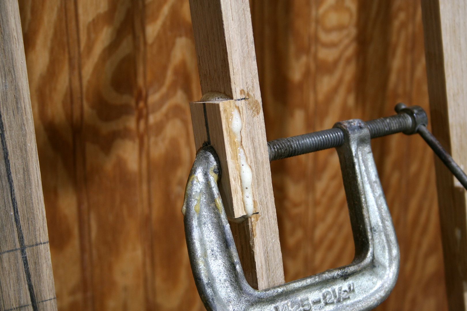
So, I switched to the traditional White Oak. I used polyurethane glue to clamp on the spacer blocks. The 2-inch long spacers were a scant 1/4-inch thick and located on 8-inch centers.

Fastener holes were pre-drilled on the press after the glue cured.

Finishing the rails involves cleaning up the excess glue, sanding, rounding the edges on a router. Since my Dad's router - from the 1950s ? - finally gave up the ghost, I had to buy a new router for my router table. (No doubt a wiring problem, the local "factory-authorized" machinery repair shop refused to touch it when I asked them to install a new cord about 10 years ago. I think my Dad and I got his money's worth....)

Stay tuned.
SJS
The next step was 'glassing the decks. Since it is always a messy job - no matter how I learn to "work clean" - I minimize the photodocumentation for the sake of my camera and tripod. Also, I followed conventional processes, to use 6-ounce cloth and epoxy resin. As I have for the past 3 or so years, I get all my supplies from U S Composites. Specifically, I use their 635 Thin Epoxy System with their 3:1 Medium Hardener.
http://www.uscomposites.com/epoxy.html
I use graduated mixing cups instead of pumps. I actually bought a set of pumps a while back but have not even ripped open the package. My applicators include foam brushes, foam rollers and squeegees. Since I am working in my shop, the wood stove ensures thorough overnight curing.
Notice that I marked out the locations of deck "appurtenances" - rails and oarlock stanchions - with a bold marker so I could locate them after the 'glassing.

My basic process is:
Day 1. Roll on a sealing coat. Let cure with temps above 70 degrees. I line interior with plastic to catch drips and dust.

Day 2. Scuff surface with 80-grit orbital sander. After cutting cloth pieces to approximate (over large) sizes, I wet an area, lay on cloth, then apply a saturation coat using a combination of brush, squeegee and roller. Let cure overnight.


Day 3. Grind overlaps and wrinkles with disc sander (60 grit) then sand entire decks with orbital sander (80 or 100 grit). I had some areas that required filler and even small patches, so I added a day. Once they cured, I rolled on a final coat of straight resin.


Day 4. Sand entire decks with orbital sander (120 or 150 grit) so they are ready to receive either paint or 3M 5200 Marine Sealant.
The next job was installing the coamings. I had made them previously (from Cypress) - and bored and countersunk the holes for screws - and sealed them with a single coat of epoxy. I also sanded them to get them ready to accept both 5200 and paint.
Installation was straightforward. I did NOT bed the coamings in 5200. Rather, I used the 5200 in the corners - as an adhesive - and laid a bead just below the deck line. My goal was to have a weathertight seal BUT not adhere the coaming to the entire face of the framing. This way, if I ever need to replace a coaming board, I can probably remove it without too much trouble.


I will round over the outside corners of the coamings - and re-seal them with epoxy - after the 5200 cures fully.

The next job was installing the rails. In this post I will cover the center line rails on the bow and stern and the toe rail for the spray dodger.
I stretched mason's twine taut to make sure the centerline rails were both on center and straight. The black markings were close but not dead on.

Next, I bored the holes for each of the fasteners. Because these center rails served several functions, fastener sizes and types varied. More than one trip to the hardware store ensued.

The rails were bedded generously with 3M 5200 allowing for plenty of squeeze out - but no voids.

Most of the fasteners were bolts backed up with washers and nuts - fender washers wherever space allowed. Some fastening required a bit of Class IV spelunking.....


The bow handle (hood ornament ?) was fastened from below with 2 s/s lag screws that run well up into the handle itself - so it can actually be used as a handle - provided the user is wearing a fresh pair of deerskin gloves.....
All excess 5200 gets wiped away before curing.


The next job encountered some head seas....

The first attempt ALMOST worked out fine. The problems began long before installation. First, I wondered if the holes required for 1/4-inch fasteners would weaken the 3/4 PVC "lumber" too much. So, when I laid out both the fastener locations and the snap locations, I told myself NOT to bore a hole in the middle of the deck. It is an especially stressful location because the toe rail - bent to its tightest radius - also crosses over a high spot on the mid-line. (The rail is 1-1/4 inches tall - to receive the snaps.) Nevertheless - the road to Davy Jones' Locker being paved with the best of intentions - the very first hole I bored on the drill press was the unforgiving centerline spot. It was in the back of my mind when I began to bolt the rail to the deck, 3M 5200 and all.
At first, I was amazed at how perfectly my process was working. I had bent the rail into its bow shape with some light line. Starting just to the left of center, I drew each carriage bolt down slowly. I could watch the rail above decks while turning the nut driver below decks. The shoulders of each bolt sank snugly into the PVC and the 5200 squeezed out as planned.
I completed the port side and then turned my attentions to the starboard rail. The head of the first bolt was a bit proud and needed some gentle persuasion - in the form of a hammer. After extricating myself from the cockpit - via step ladder - I applied just the right amount of force to the offending bolt. Just enough, it turns out, to immediately explode the rail - right at the unnecessary hole I had bored on the press......
So, off to buy some more PVC - AND to buy some lighter fasteners. Instead of 1/4-inch galvanized carriage bolts, I used 10-24 s/s panhead machine screws. The new holes are 1/8-inch instead of 1/4-inch.
The second installation went as planned. I can now post a sign at my shop door: "No catastrophic failures for 2 days....."


I have limited experience with PVC lumber. I have used it on one other toe rail. Its job is to hold the lower edge of my spray dodger. I am expecting this application will be sufficiently strong once the 5200 cures fully. I did have the thought, though, that 'glassing such a rail to the deck would probably make it truly bulletproof.
Next job is installing the port and starboard thatch rails and oarlock stanchions.
The thatch rails have been fabricated and just need sealing. I had planned to use some vertical grain Douglasfir but I lost confidence when I planed it to size.

So, I switched to the traditional White Oak. I used polyurethane glue to clamp on the spacer blocks. The 2-inch long spacers were a scant 1/4-inch thick and located on 8-inch centers.


Fastener holes were pre-drilled on the press after the glue cured.

Finishing the rails involves cleaning up the excess glue, sanding, rounding the edges on a router. Since my Dad's router - from the 1950s ? - finally gave up the ghost, I had to buy a new router for my router table. (No doubt a wiring problem, the local "factory-authorized" machinery repair shop refused to touch it when I asked them to install a new cord about 10 years ago. I think my Dad and I got his money's worth....)

Stay tuned.
SJS


